Table of Contents
Abstract
This article is about the creation of a black hole using shaders in Unity. In the start it contains a short explanation on some of the basics on HLSL in Unity. Next up there are two different parts about this shader. The first part is about the singularity and the light distortion shader and the second part contains the accretion disk shader. While combining these both together it creates one full black hole shader with a singularity, light distortion, and an accretion disk.
Introduction
Shaders are a complex but very useful thing to learn when developing games. Last semester while i was learning Virtual Reality (VR) i made a simple UI shader using shadergraph. When showing this to the team and the professor i got the feedback that shadergraph is really inefficient for performance as the smallest shaders can already have hundreds or even thousands of lines. For this reason i wanted to learn another, better, way to learn how to make shaders. For this reason i wanted to make a black hole shader including a singularity and accretion disk while using High-level shader language (HLSL).
Problem Statement
On the Amsterdam University of Applied Sciences a lot of game development students do not know how to make any kind of shaders. This is also not something that is being learned to the students. Due to this I have also never learned how to make shaders and for this reason I want to learn how to make a shader using High-level shader language (HLSL). To learn this I want to make and implement a shader with an animated black hole. The black hole will contains rings around it with a customizable color. I want to make this using HLSL so i can learn how i can use this coding implementation. Another feature that i’d like to add to this black hole shader is distortion in light so that the light goes around the black hole from the users point of view.
Research Question
How can you make an animated black hole shader including customizable color and light distortion, using High-level shader language?
Black Hole
Black holes are studied a lot but still not fully understood. The thing that is known is that they are highly concentrated, densely packed matter. The gravity beneath its surface, the event horizon, is so high that nothing can escape, not even light. [1]
Sometimes black holes are able to be surrounded by accretion disks, which are rings of dust and gas which surround the black hole. These can emit light across many wavelengths even including x-rays. These black holes can distort and bend light from more distant objects. This distortion is called, gravitational lensing. [1]
Shaders
The general idea for the shader is to have a shader for a black hole, made with High-level shader language (HLSL), which includes a customizable color and light distortion. This shader will contain 2 different parts of a black hole. Both of these parts will have to contain a new and different shader compared to the one that got used before. This will mean that there will be a shader for both the Singularity with light distortion, and the accretion disk. This shader can also be extended with a gamma ray burst but that will not be mentioned within this article.
HLSL is an, in my experience, hard language to learn due to the lack of compact and easy to read documentation. Of course there is documentation on it on some sites such as the Unity site but its in my personal opinion quite far stretched and hard to understand. Luckily i got a recommendation for some youtube video’s in a playlist which give a lot of information regarding shaders in HLSL. [2][3]
Shader Basics
Before getting into the specific shaders it is first important to know some of the basics of shaders within unity. The first important part is to know what fragment and vertex shaders are. In short, Vertex shaders are used to color vertices or to change the position of vertices. Fragment shaders are used to control per pixel colors and to change the position of pixels relative to the world position. [4]
Unity utilizes the v2f structure to generate the shader. This v2f structure contains processed data from the vertex shader. This processed data will later be used to render the final result on the fragment shader. [5]
Variables are also nice to have. To define a variable which the user can change from within the Unity editor you have to define them in the Properties to define them. The syntax is as following:VariableName ("In-Editor display name", Type(float, 2D, etc.)) = [value] {}
Additionally the user should also define the variable with the type and variable name in the pass of the shader itself. [5][6]
There is also a SubShader where users can change properties such as Tags, Culling or Level of Detail (LOD). These Tags can hold properties such as the compatibility of the shader on a Render Pipeline, Rendering Queue or the Rendering Type. [5][7]
A standard unlit shader in Unity (version 2022.3.43f1) looks like this:
Shader "Unlit/NewUnlitShader"
{
    Properties
    {
        _MainTex ("Texture", 2D) = "white" {}
    }
    SubShader
    {
        Tags { "RenderType"="Opaque" }
        LOD 100

        Pass
        {
            CGPROGRAM
            #pragma vertex vert
            #pragma fragment frag
            // make fog work
            #pragma multi_compile_fog

            #include "UnityCG.cginc"

            struct appdata
            {
                float4 vertex : POSITION;
                float2 uv : TEXCOORD0;
            };

            struct v2f
            {
                float2 uv : TEXCOORD0;
                UNITY_FOG_COORDS(1)
                float4 vertex : SV_POSITION;
            };

            sampler2D _MainTex;
            float4 _MainTex_ST;

            v2f vert (appdata v)
            {
                v2f o;
                o.vertex = UnityObjectToClipPos(v.vertex);
                o.uv = TRANSFORM_TEX(v.uv, _MainTex);
                UNITY_TRANSFER_FOG(o,o.vertex);
                return o;
            }

            fixed4 frag (v2f i) : SV_Target
            {
                // sample the texture
                fixed4 col = tex2D(_MainTex, i.uv);
                // apply fog
                UNITY_APPLY_FOG(i.fogCoord, col);
                return col;
            }
            ENDCG
        }
    }
}
The Singularity
After some of the basics mentioned before it will now be time to go into the black hole shader itself. This part will go about the singularity/the black hole itself. It will contain how to make the singularity and the light distortion around it.
The first part of the singularity which got made was the transparency and the fresnel effect. A fresnel effect is all about the angle of incidence which is the angle between your line of sight and the surface of the object your looking at. The shallower the angle, the stronger the effect. [8]
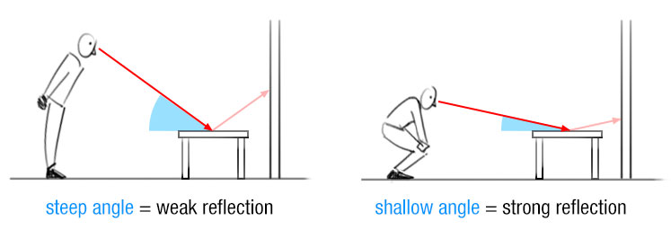
To add the fresnel effect to the shader i first added a new game object with a mesh of a sphere. Then i added a material thats connected to the shader to this object to show it. The fresnel effect is just a node in Shadergraph but in HLSL the user has to manually program it. Luckily this can be done by taking the one minus from the dot product between the normal vector and the view vector. Before any of that gets done we need to set some new variables such as the fresnel intensity or the world normals and view direction of the user. [9]
...

   Properties
   {
      _MainTex ("Texture", 2D) = "black" {}
      _FresnelAmount ("Fresnel Amount", Range(0.1, 5.0)) = 2.0
      _FresnelIntensity ("Fresnel Intensity", Range(0, 1)) = 0.5
   }

   ...

   struct appdata
   {
      float4 pos : POSITION;
      float2 uv : TEXCOORD0;
      float3 normal : NORMAL;
   };

   struct v2f
   {
      float2 uv : TEXCOORD0;
      UNITY_FOG_COORDS(1)
      float4 vertex : SV_POSITION;
      float3 worldNormal : TEXCOORD1;
      float3 viewDir : TEXCOORD2;
   };

   sampler2D _MainTex;
   float4 _MainTex_ST;
   float _FresnelAmount;
   float _FresnelIntensity;

...
After having added all the variables the next step is to convert the normals into the world space. This is important as the angles that are used should both be in the world space. Additionally the developer needs to convert the view direction from the user into world space by using matrix math. Then a variable gets made which points a vector from the vertex position towards the camera to determine the view direction.
v2f vert (appdata v)
   {
      //existing code

      o.worldNormal = UnityObjectToWorldNormal(v.normal);

      float3 worldPos = mul(unity_ObjectToWorld, v.pos).xyz;
      o.viewDir = normalize(_WorldSpaceCameraPos - worldPos);

      return o;
   }
After changing the positions to world space and checking the view direction i added the fresnel effect itself by doing a calculation which contains a dot product of the normalized world normal and the view direction. This dot product then gets clamped between 0 and 1 and then to inverse the fresnel a one minus gets applied. Lastly this value gets multiplied to the power of the _FresnelAmount variable. This full calculation will be added to the rgb of the material and then an intensity will be applied.
fixed4 frag (v2f i) : SV_Target
{
      //existing code

      float fresnelFactor = pow(1.0 - saturate(dot(normalize(i.worldNormal), normalize(i.viewDir))), _FresnelAmount);

      col.rgb += fresnelFactor * _FresnelIntensity;

      return col;
}
The last part of the fresnel is to make it transparent so that the fresnel itself is visible. This can be done by changing the queue and the rendertype to transparent and the blending to make the GPU multiply the value by 1 - source alpha. Additionally the alpha variable value also gets multiplied with the value which is going to be returned (in this case col). [10]
SubShader
{
   Tags {"Queue" = "Transparent" "RenderType"="Transparent"}

   Blend SrcAlpha OneMinusSrcAlpha
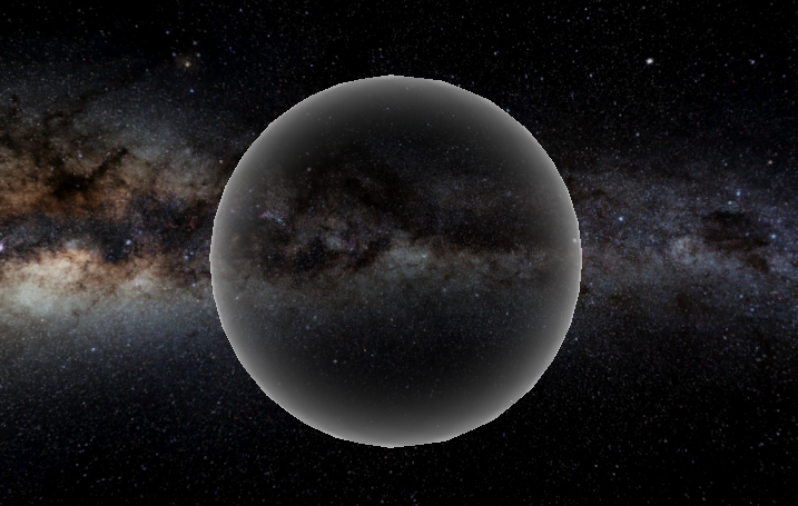
The fresnel effect is an important first step to make it possible to later define the light distortion. For this reason the next step which needs to get made is the light distortion of the black hole. For this it was first needed to add a grabpass so that the developer can use the background behind the shader. A grabpass is a function for Unity to grab the screen when it renders for the first time in a batch. This will then be added to a texture which can be used in the code. [11]
SubShader
   {

   //existing code

   GrabPass { "_GrabTexture" }
Next up for the distortion is the changes to the vertex shader. In here the normals get inverted and then get multiplied via matrix math without changing any of the positions due to the (float3x3) line. Afterward these displaced normals get added to a new variable which later gets used in the fragment shader. [9]
In the fragment shader the screenUV will be converting the screen position to normalized UV’s. Afterwards the distortion gets created by having the displacement multiplied with both the fresnel factor adn the distortion strength. The distortion will then be added to the screenUV’s and then these distorted UV’s will be added to the texture of the grab pass. [9]
v2f vert (appdata v)
{
      v2f o;
      o.pos = UnityObjectToClipPos(v.pos);

      float3 inwardNormal = -v.normal;

      float3 viewNormal = mul((float3x3)UNITY_MATRIX_IT_MV, inwardNormal);

      o.displacement = viewNormal.xy;

      o.pos = UnityObjectToClipPos(v.pos);

      //existing code

      o.screenPos = ComputeScreenPos(o.pos);

      return o;
}

fixed4 frag (v2f i) : SV_Target
{
      float2 screenUV = i.screenPos.xy / i.screenPos.w;

      //existing code

      float2 distortion = i.displacement * fresnelFactor * _DistortionStrength;

      float2 distortedUV = screenUV + distortion;

      fixed4 col = tex2D(_GrabTexture, distortedUV);

      return col;
}
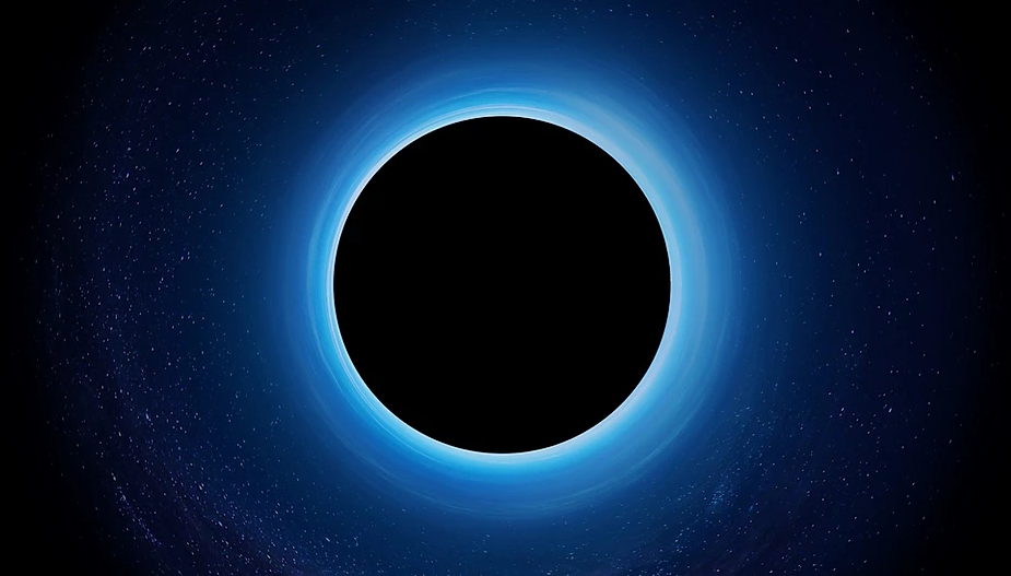
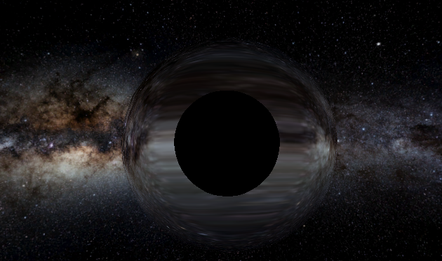
After having a working light distortion it is time to make the singularity itself. The singularity exists of the black hole part so basically just a black circle. This is something i made by adding a new _HoleSize variable and to add the fresnel factor to this to enhance the size of the singularity. This black hole then simply gets added to the texture and then you have a very basic black hole.
fixed4 frag (v2f i) : SV_Target
{
      float2 screenUV = i.screenPos.xy / i.screenPos.w;

      float fresnelFactor = 1 - pow(1.0 - saturate(dot(normalize(i.worldNormal), normalize(i.viewDir))), _FresnelAmount);

      float2 distortion = i.displacement * fresnelFactor * _DistortionStrength;

      float2 distortedUV = screenUV + distortion * step(0.01, fresnelFactor);

      float blackhole = clamp(round(fresnelFactor * _HoleSize), 0, 1);

      fixed4 col = tex2D(_GrabTexture, distortedUV + blackhole);

      return col;
}
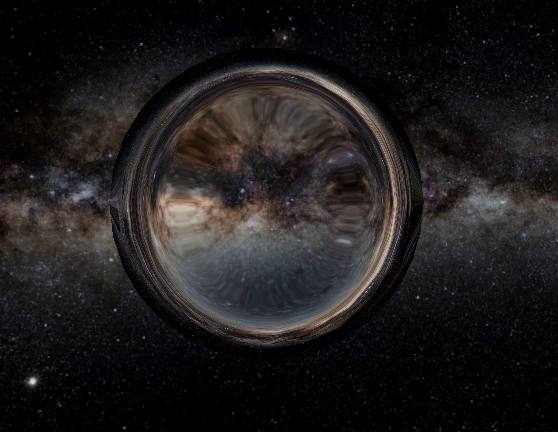
Although i made this black hole i wasn’t very happy with it yet. To fix this i could add a new feature that there’s a smoothing between the black hole and the light distortion. This made it already a bit better although it still looked a bit like an iris from an eye.
Lastly i added a slight fall off in the singularity and the light distortion so that it becomes a bit less opaque towards the edges and due to this it was made possible to make a nice singularity shader with light distortion. Lastly to scale the black hole a line got added in the vertex shader which multiplies the x, y and z values of the vertex.v.pos.xyz *= _ScaleFactor;
The Accretion Disk
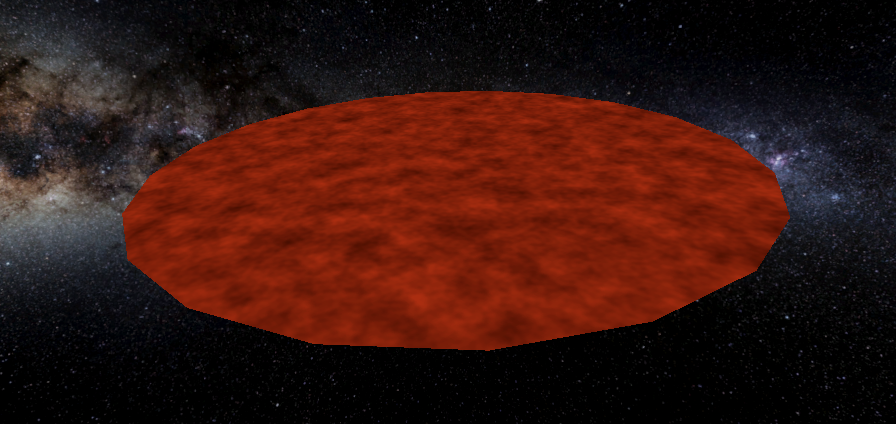
After the singularity the next step for this shader is the accretion disk. This is the disk of dust and gas that surrounds the singularity. The first step for this disk is to create a circular shape and a basic color and texture. [1]

The first version of the accretion disk is done by making a new, separate, unlit shader. This again has to be assigned to a material and set to a gameobject. The gameobject which got used in this first version was a new empty gameobject with a cylindrical mesh with a Y scale of 0 to make it circular and flat. Additionally a color will be added and a pre-generated perlin noise map texture will also be added to the texture of the accretion disk. [12]
Next up an animation for the UV’s of the disk texture got made. This got added by checking the time in seconds and changing the offset of the texture based on this time. This new animated texture then got added to the backgroundCol variable which will be returned. [13]
fixed4 frag (v2f i) : SV_Target
{
      float2 uvOffset = i.uv + float2(_Time.x, 0);

      fixed4 diskTexture = tex2D(_DiskNoiseMap, uvOffset);

      fixed4 backgroundCol = diskTexture * _Color;

      return backgroundCol;
}
Code to remove parts of the accretion disk from the middle and the outward border also got made to have it possible to remove certain parts of the disk if the user wishes to so it is customizable. How it works is the distance of the center and the _HoleOffset and the distance between the center and the _RenderRadius get compared and if it doesn’t fit between those values the vertices will get discarded. The mesh of the gameobject should now be set to a flat mesh such as a cube. A plain is also possible but keep in mind that it only has one face and due to that only renders one side.
fixed4 frag (v2f i) : SV_Target
{
   //existing code

   float dist = 1 - distance(i.uv, float2(0.5, 0.5));

   if (dist < _HoleOffset || dist > _RenderRadius)
   {
      discard;
   }
}
The next additions that i made were to improve the quality of the accretion disk. First off i added HDR coloring to make the accretion disk more saturated and stand out more. This was achieved by adding [HDR] before defining the color variable. I also added a method to even further saturate the color by a new emission variable. Lastly i also made the animation circular and added a transparency which makes the disk more transparent the more the texture goes towards the border. This is done with a smoothstep function to smooth it out. [14][15]
fixed4 frag (v2f i) : SV_Target
{
   //existing code

   float transparency = 1.0 - smoothstep(0.0, 1.0, radius);

   //existing code
}
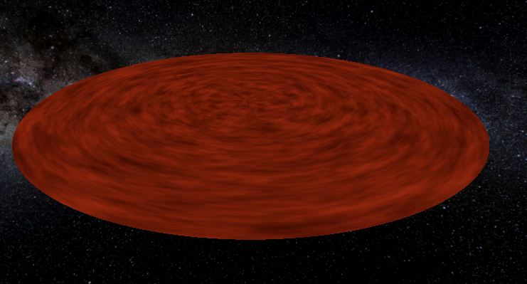
Due to a low quality quality perlin noise map the texture of the accretion disk was also relatively low. To enhance this i added a higher quality perlin noise map to make it more detailed. [12]
Next up i made the animation better circular so that it also moves into the black hole instead of it only moving around it. Only downside to the atan2() function in this case is that there is a specific line which doesn’t follow the texture. This can be fixed by using sine and cosine instead but in my opinion the texture becomes less nice when using that.
fixed4 frag (v2f i) : SV_Target
{
   //existing code

   float2 uvAnimation = float2(atan2(uv.y, uv.x) / UNITY_PI + 0.5, radius) +
   (radius + _Time.x);

   //existing code
}
Lastly to scale the accretion disk a line got added in the vertex shader which multiplies the x, y and z values of the vertices.v.pos.xyz *= _ScaleFactor;
Results
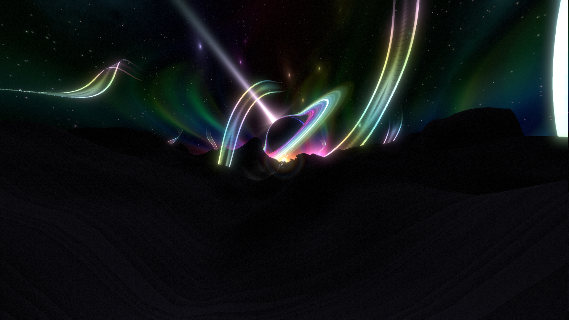
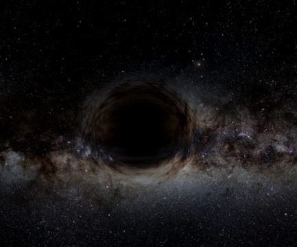
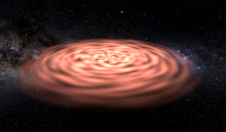
By adding both shaders and gameobjects together this is the final result. The orange line around the singularity is also not needed to make separately as the light distortion will automatically distort the line around the singularity due to the two things overlapping.
Conclusion
By using High-level shader language (HLSL) i made an animated black hole shader using a singularity and an accretion disk. The singularity has light distortion and due to this distorts the light around it. The singularity also has a high level of customizability due to the user being able to change a lot of variables. The accretion disk is also customizable with for example the color, the emission and the size.
Here is the final gif of the full black hole:
Reflection
I’m happy with the product that got made but there are some things i would like to improve for the next time i work on this. First off, i’d like to write some more documentation at the start as i started a bit later on in the project which means that some parts are documented later onwards while i now think its better to instantly document everything.
I also want to do a short research into which rendering pipeline is good for a shader as i had to switch the render pipeline in the middle of the project as URP had issues with working with the grab pass function.
Future work
For future work this shader could be extended with some possible performance optimization. I don’t think this is a big issue as of now but i haven’t looked into the possible performance of the shader.
Another point could be to make the accretion disk volumetric instead of flat as it is right now. By making it volumetric it just gets more volume and looks nicer. In addition to this the light distortion of the accretion disk around the singularity could also be slightly more intense as i now feel like the disk is quite narrow at that point.
Lastly is a third feature of the black hole which is the gamma ray burst which didn’t get made. This can give even more atmosphere to the black hole shader by adding a full new component to it.
References
[1] J. Kazmierczak, “Black Holes - NASA Science”, NASA Science, 8 mei 2024. https://science.nasa.gov/universe/black-holes/
[2] U. Technologies, “Unity - Manual: Writing shaders in code”. https://docs.unity3d.com/6000.0/Documentation/Manual/shader-writing.html
[3] Dapper Dino, “Creating shaders”, YouTube. https://www.youtube.com/playlist?list=PLS6sInD7ThM3giqACaYCBtIhkMNucqmna
[4] A. Schrute, “Vertex Fragment Shader Structure - Shader Coding in Unity from a to z - Medium”, Medium, 13 december 2021. https://medium.com/shader-coding-in-unity-from-a-to-z/vertex-fragment-shader-structure-fde81b67d18f
[5] Afterverse, “Introduction to Shaders - Beyond - Medium”, Medium, 22 januari 2022. https://medium.com/beyond-afterverse/introduction-to-shaders-beb722579876
[6] H. Zhou, “Unity accessing HLSL shader parameters with C# Input Controller”, Medium, 13 december 2021. https://heran-zhou.medium.com/unity-accessing-hlsl-shader-parameters-with-c-input-controller-baadc9b840c6
[7] U. Technologies, “Unity - Manual: SubShader tags in ShaderLab reference”. https://docs.unity3d.com/Manual/SL-SubShaderTags.html
[8] D. Iten, “Understanding the Fresnel Effect – Dorian Iten”. https://www.dorian-iten.com/fresnel/
[9] M. Gutierrez, “Blackhole Shader in Unity - Mario Gutierrez - medium”, Medium, 4 januari 2025. https://medium.com/@mariosubspace/blackhole-shader-in-unity-eb7d93af9577
[10] U. Technologies, “Unity - Manual: Blend command in ShaderLab reference”. https://docs.unity3d.com/Manual/SL-Blend.html
[11] U. Technologies, “Unity - Manual: GrabPass directive in ShaderLab reference”. https://docs.unity3d.com/Manual/SL-GrabPass.html
[12] M. McKay, “Noise maker”. http://kitfox.com/projects/perlinNoiseMaker/
[13] U. Technologies, “Unity - Manual: Built-in shader variables reference”. https://docs.unity3d.com/Manual/SL-UnityShaderVariables.html
[14] U. Technologies, “Unity - Manual: Properties block reference in ShaderLab”. https://docs.unity3d.com/Manual/SL-Properties.html
[15] “SmoothStep Node | Shader Graph | 6.9.2”. https://docs.unity3d.com/Packages/com.unity.shadergraph@6.9/manual/Smoothstep-Node.html