Procedural Racetrack Generation
1. Introduction
Procedural Content Generation (PCG) is widely used in games to increase replayability while reducing manual authoring time. In the context of racing games, PCG introduces a particularly complex challenge: racetracks must not only be visually convincing, but also structurally valid, readable at high speeds, and compliant with real-world racing constraints.
Unlike many procedurally generated environments, racetracks form a continuous closed-loop system in which errors such as self-intersections, extreme angles, or inconsistent curvature immediately break immersion and gameplay. This makes naïve random generation approaches unsuitable for realistic racing scenarios.
The goal of this research is to explore how procedural generation techniques can be applied to create structurally valid, non self-intersecting racetracks, while still allowing for variation, designer control, and dynamic track elements such as adaptive gravel traps.
1.1 Defining Realistic Racetrack Constraints
To evaluate procedural racetrack generation methods, several constraints were defined based on real-world racing design principles and practices in existing circuits. One fundamental requirement in real-world racing tracks is the closed-loop system. A racecar should be able to complete laps around a circuit, without crossing over itself. For procedural generation this means that the first and last segment of the track should connect smoothly [1].
Another critical constraint is the concept of self-intersections. In real-world racetrack design, track crossings are prohibited for safety and readability reasons. In procedural systems, self-intersections commonly arise when points are generated freely in two-dimensional space and later connected. Prior work on procedural racetrack generation highlights that intersection handling often requires costly validation or correction steps, such as collision checks or segment intersection tests [1], [2].
In addition, readable corner transitions are essential for realistic racing experiences. Corners should transition smoothly from one to the next, avoiding sudden angle changes that would be physically implausible at racing speeds. Bézier curves and spline-based representations are frequently used in game development to ensure smooth curvature and controllable transitions between track segments [3], [4].
From a design perspective, procedural systems must also support controlled variation. While randomness is important for replayability, unconstrained randomness often leads to chaotic or unusable results. Random scattering techniques address this by distributing points stochastically while enforcing spatial constraints, enabling variation without structural collapse [5]. However, such techniques typically operate on open environments rather than closed-loop systems.
1.1.1 Realistic Tracks
Before addressing procedural generation, it is important to clarify what defines a racetrack, specifically an FIA-grade circuit, and why its structure matters. A racetrack is not merely a closed loop for vehicles to circulate on; it is a carefully designed environment intended to create competitive racing, strategic decision making, and clear opportunities for driver skill to emerge.
One of the primary goals of racetrack design is to facilitate overtaking opportunities. This is commonly achieved through the combination of long straights followed by heavy braking zones, where drivers can attempt high-risk, high-reward overtakes. Equally important are technical sections, consisting of sequences of corners with varying radii and directions. These sections test car control, precision, and consistency, often leading to time gains or mistakes that influence race outcomes.
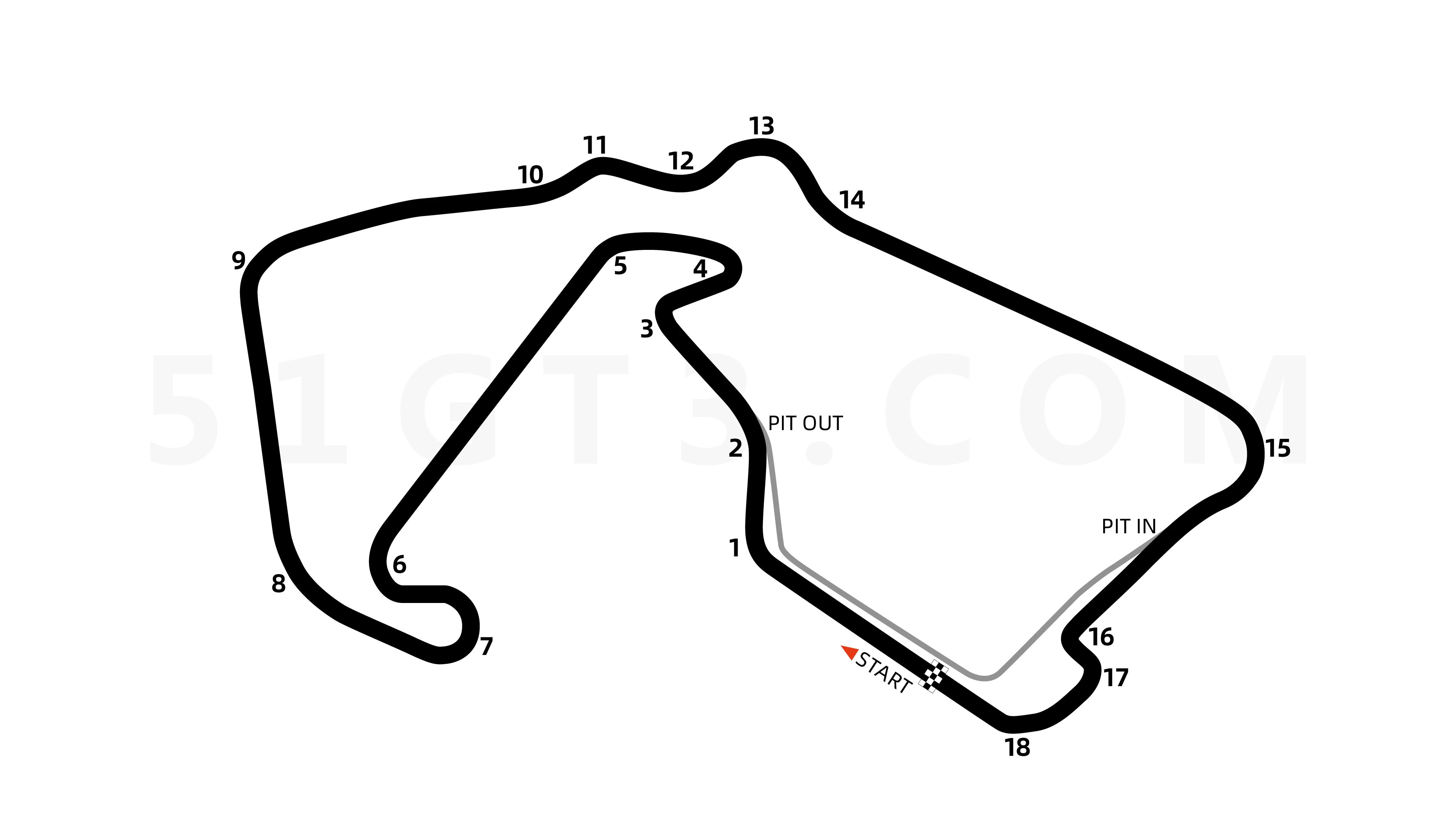
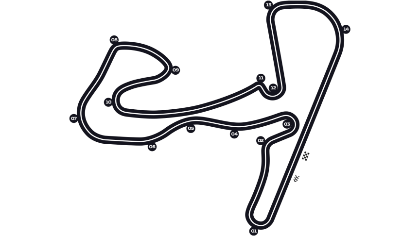
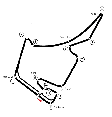
Real-world circuits such as Silverstone Circuit, Circuit Zandvoort, and Hockenheimring illustrate these principles clearly. At Silverstone, high-speed corner sequences demand aerodynamic stability and driver confidence, while Zandvoort emphasizes flowing corner chains and rhythm. The Hockenheimring historically combined long straights with tight chicanes, explicitly designed to create braking-based overtaking zones. These examples highlight how the ordering and relationship between corners and straights are central to effective circuit design.
1.2 Research Question
How can procedural content generation be used to generate realistic, non-self-intersecting racetracks on demand, while allowing dynamic components such as corner sharpness, barriers, and scenery?
1.3 Overview of Approaches
Three procedural approaches were explored:
- Unconstrained random point generation with correction
- Point repulsion and boundary enforcement
- Constraint driven circular segmentation (final)
The first two approaches relied on detecting and fixing invalid configurations after generation. The final approach instead embeds structural guarantees directly into the generation space itself.
2. Early Approaches
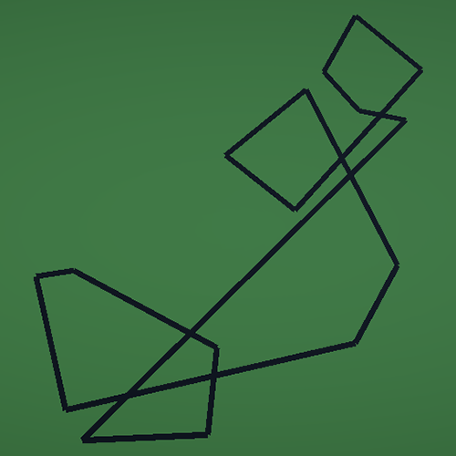
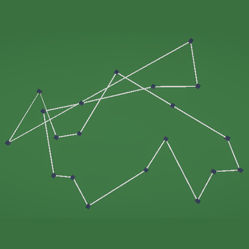
Before arriving at the final constraint-driven approach, several procedural generation strategies were explored that relied on post-generation correction to achieve valid racetrack layouts. These methods attempted to generate tracks freely and subsequently detect or resolve invalid configurations such as self-intersections, overly sharp corners, or clustered geometry.
This section describes these early approaches, the concrete steps involved in their implementation, and the limitations that motivated a shift in methodology.
2.1 Unconstrained Sequential Point Generation
The first approach generated racetracks by incrementally extending a path using straight segments and corners, similar to a constrained random walk.
Algorithmic Steps:
- Start at an origin point with a forward direction
- Alternate between straight segments and corner segments
- Rotate the direction by a random angle for corners
- Add new points sequentially
- Validate each new segment against all previous segments
Core generation logic:
Vector3 currentPoint = Vector3.zero;
Vector3 direction = Vector3.forward;
List<Vector3> points = new List<Vector3>();

for (int i = 0; i < numberOfSegments; i++)
{
    float angle = Random.Range(minAngle, maxAngle);
    float length = Random.Range(minLength, maxLength);

    direction = Quaternion.Euler(0, angle, 0) * direction;
    Vector3 nextPoint = currentPoint + direction * length;

    if (!SegmentIntersects(points, currentPoint, nextPoint))
    {
        points.Add(nextPoint);
        currentPoint = nextPoint;
    }
}
Intersection Detection:
bool SegmentIntersects(List<Vector3> points, Vector3 start, Vector3 end)
{
    for (int i = 0; i < points.Count - 1; i++)
    {
        if (LinesIntersect(start, end, points[i], points[i + 1]))
            return true;
    }
    return false;
}
As seen here, to prevent crossings each new generated segment was tested against all existing segments. This works pretty well for a small number of segments, but the computational complexity grows very fast as the track becomes longer.
Points of failure
Complexity
Each new segment is tested against all previous ones.
Later-stage failure
Intersections often occur near the end of generation, invalidating large portions of the track at once.
Unstable parameter space
Small changes in angle or length ranges dramatically affect success rate.
These issues are consistent with correction-based racetrack generation approaches described by Gallostra and Maciel [1], [2].

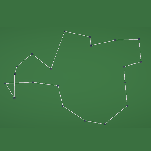
2.2 Point Repulsion
After seeing the instability and performance issues of direct intersection checking, a second approach was explored that attempted to reduce invalid geometry by improving point distribution, rather than rejecting segments outright.
This approach introduced a post-processing relaxation step, in which points that were generated too close to one another were pushed apart to enforce a minimum spacing constraint.
Algorithmic Steps:
- Generate an initial sequence of track points using a random-walk style method
- Allow both straight segments and corner segments with randomized angles and lengths
- Store all generated points without validating intersections during generation
- After generation, iterate over all point pairs
- If two points are closer than a minimum distance:
- Push one point away from the other along their connecting vector
- Use the adjusted point set as control points for mesh generation
Core generation logic:
The initial point placement followed a sequential process similar to the first approach, but without immediate intersection checks:
Vector3 currentPoint = Vector3.zero;
Vector3 direction = Vector3.forward;
List<Vector3> points = new List<Vector3>();

for (int i = 0; i < pointCount; i++)
{
    float angle = Random.Range(minAngle, maxAngle);
    float length = Random.Range(minLength, maxLength);

    direction = Quaternion.Euler(0, angle, 0) * direction;
    Vector3 nextPoint = currentPoint + direction * length;

    points.Add(nextPoint);
    currentPoint = nextPoint;
}
At this stage the algorithm prioritizes speed and flexibility, postponing structural validation until all points are generated.
Point repulsion logic:
To prevent the clustering of points, and the intersections in the track, spatial relaxation was applied:
void PushPointsApart(List<Vector3> points, float minDistance)
{
    for (int i = 0; i < points.Count; i++)
    {
        for (int j = i + 1; j < points.Count; j++)
        {
            float distance = Vector3.Distance(points[i], points[j]);

            if (distance < minDistance)
            {
                Vector3 direction = (points[j] - points[i]).normalized;
                float pushAmount = minDistance - distance;

                points[j] += direction * pushAmount;
            }
        }
    }
}
This method enforces a local spacing constraint, similar to to techniques used in constrained random scattering to prevent point clustering [5].
Intended Benefits
Switching from validation at each generated point to this spatial relation method, was with the intent of:
- Reduce extreme clustering of control points
- Improve spacing between corners
- Lower the probability of self-intersections
Points of failure
Loss of track flow and intent
Because points are displaced after the generation, the original logic of the track is being altered. This can result in the intent of the track building is lost.
No global structuring
While the local spacing improved, the algorithm provided no guarantees regarding the absence of self-intersections and the logical ordering of corners.
Computational cost
Even though this method is less computational heavy in comparison to the previous method, it still faces high cost due to pairwise distance comparisons.
3. Final Approach
The limitations of the earlier approaches led to some fundamental problems that made me switch to a completely different approach. Instead of generating points almost freely and trying to fix it later on, I used a technique to rule out the possibility of these crossovers completely. This chapter explains how I built a constraint-driven method to generate racetracks which form an actual layout. By embedding the constraints directly in the generation process, the algorithm guarantees a closed-loop without intersections.
3.1 Design Philosophy
After sitting down, looking at my failed attempts, I was talking to my classmate and we thought of a constraint-driven method. During the conversation I realised that if I forced the generation of the points to be in a cicular shape, with each point being freely picked within a “slice”, the track could never go over itself (see image).
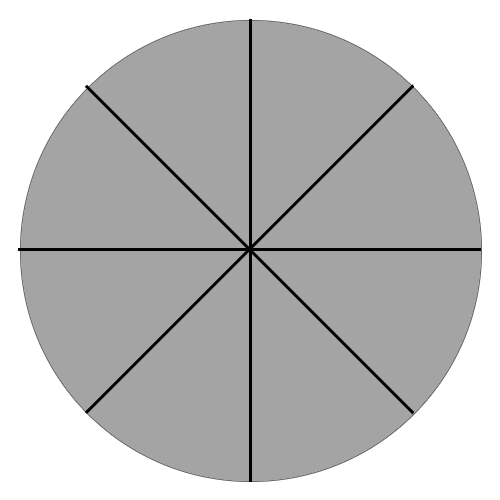
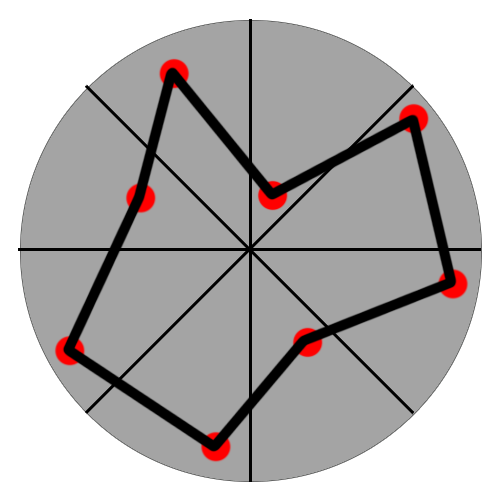
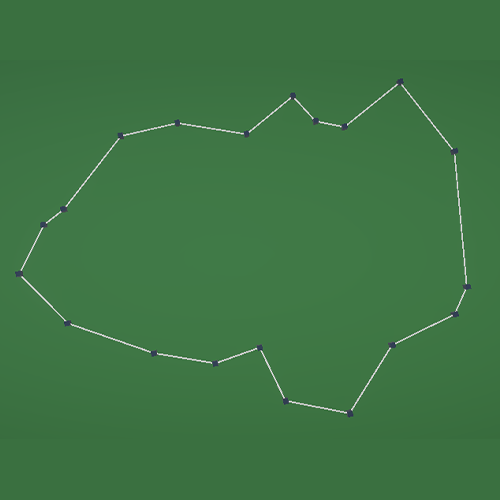
Left Image
As seen in the first image, the circular generation is divided into a fixed number of segments (like slices). Each slice represents a reserved space in which a “point” can be generated. At this stage, no points are placed yet. The figure just shows what the first step of the algorithm is. By assigning each control point to a certain area, we can already rule out the intersections, as the points are connected clockwise.
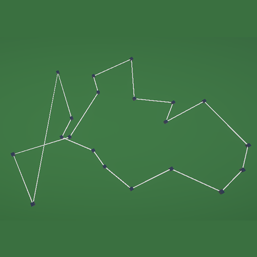
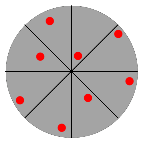
Middle Image
As said in the explanation about the first image, in each of the slices a single control point (red dot) is placed. The point can be placed anywhere in the slice, but this variability can be suppressed in the settings of the algorithm. Boundaries such as the minimum and maximum distance from the middle point can be tweaked. This provides the randomness that we want to see from procedural generation, but in a controlled way where they are not able to overlap each other.
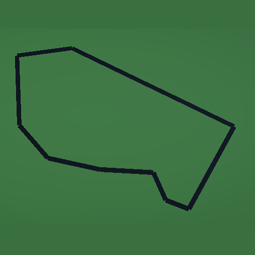
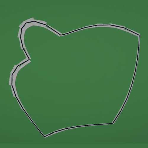
Right Image
The final racetrack is constructed by connecting the control points sequentially in angular order (clockwise). The final segment naturally connects back to the first, closing the loop and forming the final racetrack. This approach ensures there is no way for the track to cross over itself, and thereby is a valid track.
3.2 Implementation
To implement the constraint-driven approach, I created a script that generates one control point per angular slice, and stores the resulting positions for later mesh generation.
Algorithmic Steps
- Clear previously generated points and data
- Compute the angular width per slice
- For each slice i
- Sample a random angle within the slice bounds
- Sample a random radius within
- Convert polar coordinates to a world position
- Instantiate a visible point prefab
- Store the position in a list (for later mesh generation)
- Pass the control points to the mesh builder
Clear previous points
To make sure there are no double tracks, all previously generated points are cleared.
for (int i = 0; i < spawnedPoints.Count; i++)
        {
            if (spawnedPoints[i] == null) continue;

            if (Application.isPlaying) Destroy(spawnedPoints[i]);
            else DestroyImmediate(spawnedPoints[i]);
        }

        spawnedPoints.Clear();
Divide Circle into Slices
The circular generation space is divided into equal angular segments. Each segment represents a reserved space where only one control point can be placed.
float angleStep = 360f / numberOfPoints;
Defining the Angular Bounds
For each slice i, the angular interval is defined. Control points are restricted to this interval.
float startAngle = (i * angleStep) * Mathf.Deg2Rad;
float endAngle   = ((i + 1) * angleStep) * Mathf.Deg2Rad;
Sampling a Point per Slice
Within the angular bound of the slice, a control point is placed using bounded randomness.
float randomAngle  = Random.Range(startAngle, endAngle);
float randomRadius = Random.Range(minRadius, maxRadius);
The angle controls the point’s position within the slice, while the radius determines how close the point is to the center of the circle. The radius bounds can be adjusted to influence the overall shape of the track.
Converting to World Space
The sampled polar coordinates are converted to a position in world space.
Vector3 pointPosition = new Vector3(
    Mathf.Cos(randomAngle) * randomRadius,
    0f,
    Mathf.Sin(randomAngle) * randomRadius
);
At this stage, the control point is fully defined and can be visualized or stored for further processing.
This rules out every possibility for the track to cross over itself, as the strict order by angle and the clockwise connection prevents any possibility to cross over (see image in 3.1).
3.3 Mesh Generation
After generating a valid set of ordered control points using circular segmentation, the next step is to convert this abstract layout into an actual racetrack surface. This is achieved by constructing a mesh that follows the generated control points and gives the track physical width.
The mesh generation step does not alter the layout of the track, it purely operates on the guaranteed-valid control points produced by the previous stage.
Algorithmic Steps
- Receive the ordered list of control points
- For each control point:
- Compute a forward direction based on neighboring points
- Compute a perpendicular vector to define track width
- Offset the control point to the left and right from track edges
- Store the resulting vertices
- Connect vertices into triangles to form the track surface mesh
- Assign the generated mesh to a
MeshFilterfor rendering
Computing Direction
To determine how the track should be oriented at each control point, a direction vector is computed based on the surrounding points. This allows the mesh to smoothly follow the shape of the track.
Vector3 forward = (nextPoint - previousPoint).normalized;
Using both the previous and next point ensures that the direction reflects the local curvature of the track rather than abrupt changes.
Computing Track Width
Once the forward direction is known, a perpendicular vector is computed to define the left and right edges of the track.
Vector3 right = Vector3.Cross(Vector3.up, forward).normalized;
This perpendicular vector is then used to offset the control point to both sides:
Vector3 leftVertex  = point - right * (trackWidth * 0.5f);
Vector3 rightVertex = point + right * (trackWidth * 0.5f);
By repeating this for every control point, two parallel vertex strips are created that define the edges of the racetrack.
Building the Mesh Geometry
The generated vertices are connected into triangles to form a continuous surface. Each pair of consecutive points forms a quad, which is split into two triangles.
triangles.Add(i * 2);
triangles.Add(i * 2 + 2);
triangles.Add(i * 2 + 1);

triangles.Add(i * 2 + 1);
triangles.Add(i * 2 + 2);
triangles.Add(i * 2 + 3);
This process is repeated for all segments, including the final connection from the last point back to the first, ensuring a closed-loop mesh.
Mesh Output
Mesh mesh = new Mesh();
mesh.vertices = vertices.ToArray();
mesh.triangles = triangles.ToArray();
mesh.RecalculateNormals();

meshFilter.mesh = mesh;
At this stage, the racetrack exists as a continuous, renderable surface that accurately follows the constraint-driven layout.

3.4 Adaptive Gravel Traps
Once a valid racetrack mesh is generated, additional trackside elements can be derived from the same control points. One such element is the gravel trap, which serves both a functional and visual purpose in real-world racing circuits. Gravel traps are typically placed on the outside of corners, with sharper corners requiring larger run-off areas. In real world circuits this is because tight corners are often followed after a long straight, which in turn makes for high approaching speeds.
In this project, gravel traps are generated procedurally based on the local curvature of the track, allowing them to adapt automatically to different track layouts.
Algorithmic Steps
- Iterate over each control point along the track
- Compute the angle between the incoming and outgoing track segments
- Use this angle as in indicator of corner sharpness
- Scale the gravel trap size based on the computed sharpness
- Generate gravel geometry offset from the outer edge of the track
Detecting Corner Sharpness
To determine how demanding a corner is, the angle between the direction vectors before and after a control point is calculated.
Vector3 dirToPrev = (currentPoint - previousPoint).normalized;
Vector3 dirToNext = (nextPoint - currentPoint).normalized;

float cornerAngle = Vector3.Angle(dirToPrev, dirToNext);
A larger angle corresponds to a sharper turn while small angles indicate a more steep curve.
Mapping Corner Sharpness to Gravel Size
The computed corner angle is mapped to a stretch factor that controls how far the gravel trap extends away from the track.
float stretchFactor = Mathf.Lerp(minStretch, maxStretch, cornerAngle / 90f);
This mapping ensures that gentle bends receive minimal gravel coverage, and sharp corners get the larger run-off areas.
Positioning the Gravel Trap
Gravel traps are positioned on the outside of each corner. The outside direction is determined using the track’s forward direction and a perpendicular vector.
Vector3 forward = (nextPoint - previousPoint).normalized;
Vector3 outward = Vector3.Cross(forward, Vector3.up).normalized;
The gravel geometry is then offset from the track edge along this outward direction, scaled by the stretch factor.
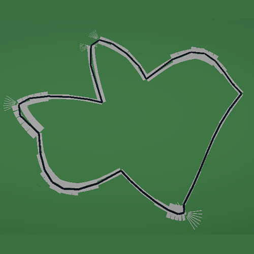
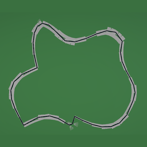
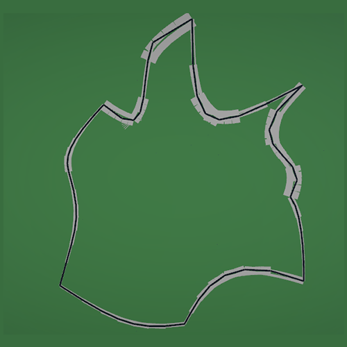

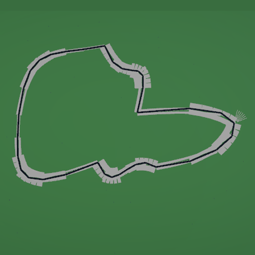
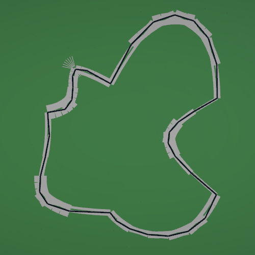
3.5 Showcase Different Parameters
To show what the difference is in output, based on the parameters I will show some generations with different parameters but the same seed.
The variable Number of Points is the amount of control points that are generated.
The variable Radius is the distance the edge of the circle is to the middle of the circle.
The variable Minimum Distance from Center is the distance that each point is required to have from the middle point.
Number of Points: 15
Radius: 450
Minimum Distance from Center 10
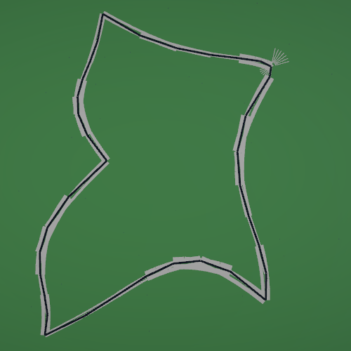

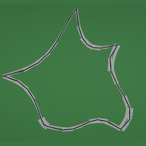
Number of Points: 25
Radius: 450
Minimum Distance from Center 10

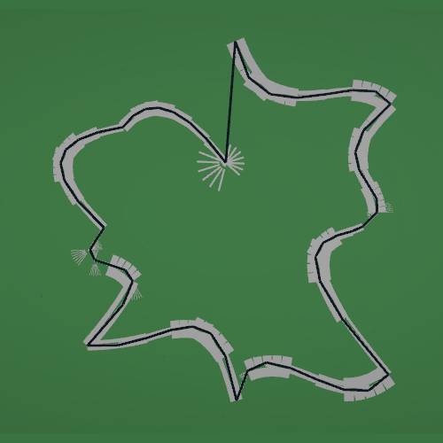

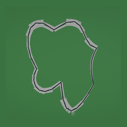
Number of Points: 15
Radius: 650
Minimum Distance from Center 10
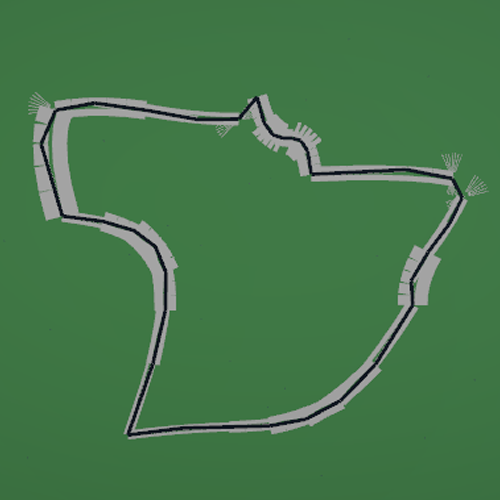
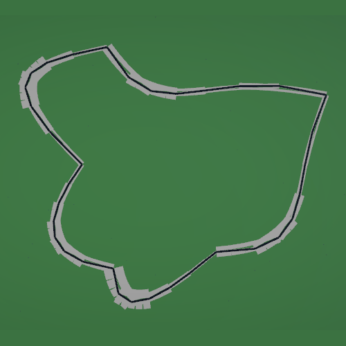
Number of Points: 15
Radius: 450
Minimum Distance from Center 60
4. Conclusion and Reflection
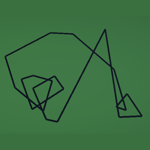
This research explored multiple procedural content generation approaches for creating racetracks, with the goal of producing realistic, non self-intersecting, closed-loop layouts suitable for racing games. Early methods based on unconstrained point generation and post-generation correction revealed significant limitations, including unstable behavior, high computational cost, and a lack of structural guarantees.
The final constraint-driven approach addressed these issues by embedding validity directly into the generation process. By modeling the track layout as a circular space divided into angular slices, the algorithm guarantees correct ordering, loop closure, and the absence of self-intersections by construction. This shift from validation-based to constraint-based generation proved to be the key insight of the project.
Separating the generation pipeline into distinct stages under which: layout generation, mesh construction, and adaptive gravel trap placement resulted in a modular and extensible system. Each stage operates on guaranteed-valid data, eliminating the need for corrective logic and making the system easier to reason about, modify, and extend.
From a design perspective, the approach balances randomness and control. Variation is achieved through bounded randomness within each slice, while global structure remains predictable. This allows both programmers and designers to influence the resulting track layout without risking invalid configurations.
Sources
[1] J. Gallostra, “Procedural Racetrack Generation,” Bites of Code, Apr. 2020. [Online]. Available: https://bitesofcode.wordpress.com/2020/04/09/procedural-racetrack-generation/
[2] G. Maciel, “Generating Procedural Racetracks,” Game Developer, 2021. [Online]. Available: https://www.gamedeveloper.com/programming/generating-procedural-racetracks
[3] J. Catlike Coding, “Curves and Splines,” 2018. [Online]. Available: https://catlikecoding.com/unity/tutorials/curves-and-splines/
[4] “How to Work with Bézier Curves in Games with Unity,” Game Developer, 2019. [Online]. Available: https://www.gamedeveloper.com/business/how-to-work-with-bezier-curve-in-games-with-unity
[5] M. West, “Random Scattering: Creating Realistic Landscapes,” Game Developer, 2017. [Online]. Available: https://www.gamedeveloper.com/business/random-scattering-creating-realistic-landscapes