Semi Realistic Chandelier Shader in Godot
Tamira Verheul
HBO-ICT Game Development
Hogeschool van Amsterdam
Nederland, Amsterdam
Abstract - This paper is about making a semi realistic chandelier shader in Godot. It’s intended for horror applications, and should be high performance, in order to not break immersion on lower-end devices.
keywords - godot, chandelier, horror, crystal, projection
Introduction
In most (indie) horror games, indoor lighting is done by having some kind of strange, glowing orb surrounding the player. This is done so the lights in the scene do not have to be point lights, but this strange light near the player is very immersion breaking. This will be especially difficult with the chandelier I’m going to be using for my shader. The chandelier needs to be able to shimmer, making it look semi realistic. The way it shimmers should depend on how the player looks at it. I want this to work in Godot, as I no longer use Unity outside of school. Another thing that would be needed for the immersion is the refraction of the crystals that’s visible on the ground. (fig. 1)
 Figure 1
Problem Statement
Godot doesn’t support all of the same features Unity does (ex. Grab Pass) and uses their own shading language, which may be easier to understand, but is a bit more limited. I’d like to see how far it can be pushed to make the closest to realistic chandelier shader possible. This shader needs to:
- Have decent performance
- Seemingly real time reflections
- Flickering candles
- Beforementioned refraction on other objects
This leads to the research question: What is the best looking chandelier shader that can be built in Godot?
To make this more manageable this will be split up in the following parts:
- The base, containing the chandelier and it’s internal reflections and refractions.
- The flickering candles.
- The refraction on other objects.
- Performance
Base
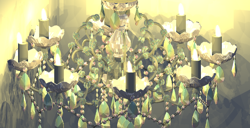 Figure 2
I’m using the chandelier shader I previously made for Unity as a base(fig. 2), but since Godot uses a different shading language it needs to be converted. GDShader script is similar to Unity’s shader script, but it has some slight differences that make it odd to work with when starting out. The main notable difference is that Godot doesn’t support Grab pass, which is something my Unity shader quite heavily relied on. To deal with this, I made a very simplistic simulation, based on the main texture and the screen uv. Godot’s screen texture could be similar to Unity’s Grab Pass, but ignores transparent objects, which could lead to weird results since the entire chandelier will be transparent.
In order to simulate refraction without Grab Pass, I’m using Godot’s SCREEN_UV. This is the position of the object on the screen. I multiply this with the normal, and use that to make it seem like there’s refraction, without actually having refraction.
vec2 refracted_uv = SCREEN_UV.xy + NORMAL.xy * 0.1;
vec4 refr_color = texture(main_tex, refracted_uv);
vec4 final_color = mix(refr_color, base_color, base_color.a);
The color and reflection are simulated using a rainbow image and one with two lines, to make for a cartoony fake reflection, that works incredibly well for the chandelier.
I also combine this with a normal map for the entire object, helping the more rounded areas refract correctly. This is a comparison between the current product in Godot (fig. 3), and the product originally made in Unity (fig. 4).
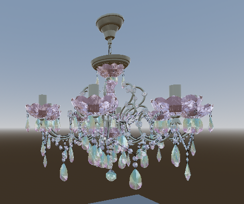 Figure 3
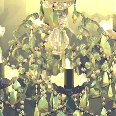 Figure 4
Candles
Converting the code I used for the candles in Unity was a bit interesting as I used the screen position in unity to move the candles, and the version of that that’s built in in Godot is bugged for transparent and semi-transparent objects. I chose to program it myself, as it seemed like something I might need in the future as well. I used the following code:
vec4 clip_pos = MODELVIEW_MATRIX * vec4(VERTEX, 1.0);
vec4 ndc_pos = PROJECTION_MATRIX * clip_pos;
vec2 screen_pos = (normalized_pos.xy / normalized_pos.w) * 0.5 + 0.5;
Modelview_matrix is a built in variable that contains a combination of the object space to world space matrix and the world space to camera space matrix. Since this comes in a mat4, we need to convert the vertex vector to a vec4 in order to be able to multiply. We need the object space to camera space, that’s why we need to do this math.
After this step we need to go from camera space to clip space, which according to LearnOpenGL [1] is done by multiplying our current value with the projection matrix. This is often called NDC, which stands for Normalized Device Coordinates.
The website mentioned earlier talks about both orthographic and perspective projections, for our case we need perspective, as this mimics the real world, where orthographic doesn’t. Now the only step we still need to do is convert our vec4 to a vec2, as a screen only has 2 dimensions. The website mentions this is done by dividing xyz coordinates with w coordinate. In this specific case the z isn’t used, as that isn’t visible when converting to 2d. The website also mentions that their desired range for coordinates is between -1 and 1, but most screen spaces range between 0 and 1, which is why we multiply by 0.5 and add 0.5, this ensures the values fall within the correct range.
This screen position can now be used to convert the original Unity code to Godot, leading to candles that slightly wave (fig. 5).
This effect was created by using a sinus wave to offset the screen position based on time.
Lighting works rather different in Godot than it did in Unity. In Unity the light for the base with candles was created by simply creating the eight light sources and that was really it. In Godot that lead to a couple problems, visible in figure 6.
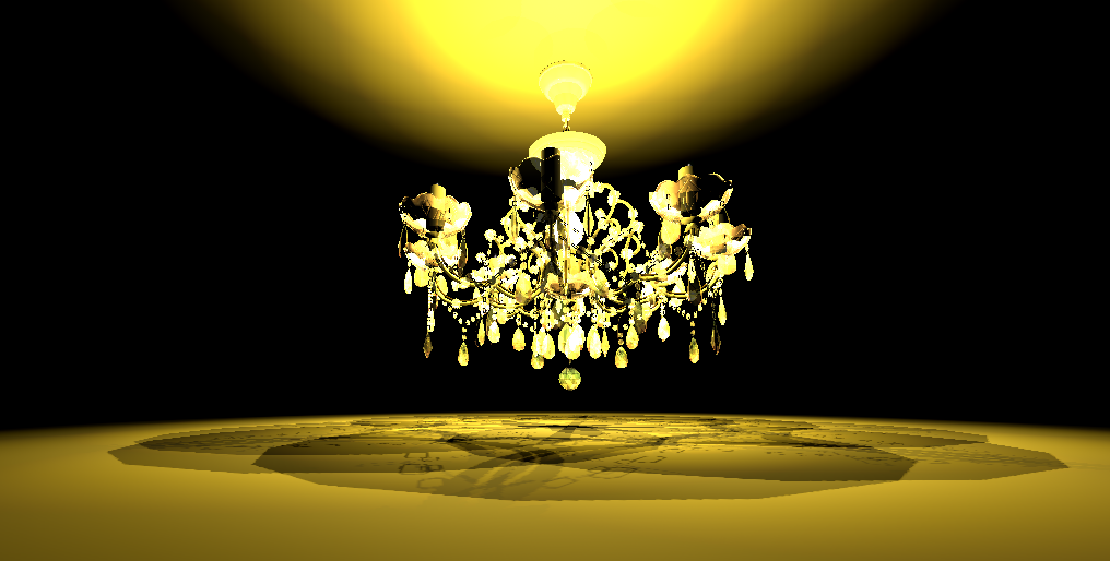 Figure 6
Although this does arguably already look more like something for a horror game than the final version in Unity, this has some very clear problems:
- It’s very over lit
- The floor is missing shadows for all crystals
- Somehow the light appears to be coming from the ceiling, when it is in fact coming from the candles
Initial thought would be to turn down the range of the light, which made the entire room dark, but the chandelier still looks like a fireball, as seen in figure 7.
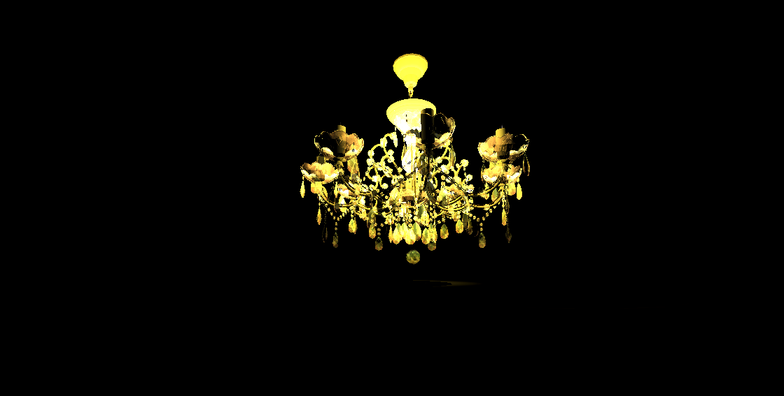 Figure 7
Since the chandelier in figure 6 doesn’t have shadows, this could be a cause for how over lit it seemed. According to Godot’s official documentation [2] Godot doesn’t generate shadows for objects with an alpha value lower than 1.0. In order to fix this the render mode needs to be set to depth_prepass_alpha. The version with shadows (fig. 8) looks a lot better, but still looks rather over lit. The shadows have also appeared to make the lower ball invisible. The final point is that some of these shadows are very pixelated.
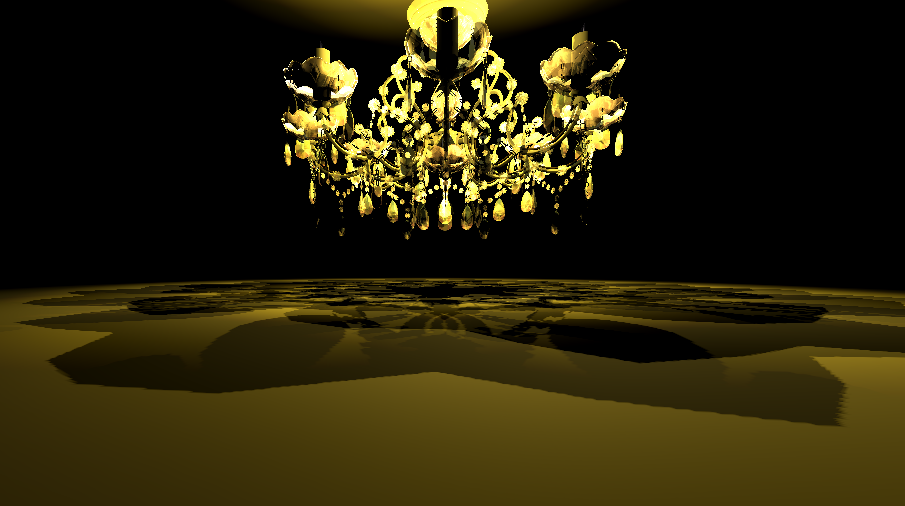 Figure 8
In a real chandelier, the crystals do also glow a little (fig. 9), but not as much as the current product. Raising the attenuation and making the object darker made it look a lot better, as seen in figure 10.
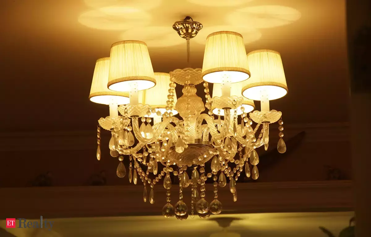 Figure 9
 Figure 10
The shadows can be improved by simply increasing the size of the shadow map Godot generates.
Comparing this (fig. 11) to the Unity version (fig. 12), the current version looks significantly more like something for a horror game.
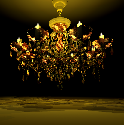 Figure 11
 Figure 12
Refraction on other objects
For this shader/project I’d like the light to be refracted onto other surfaces as well, in the way these sort of crystals usually do(fig. 13).
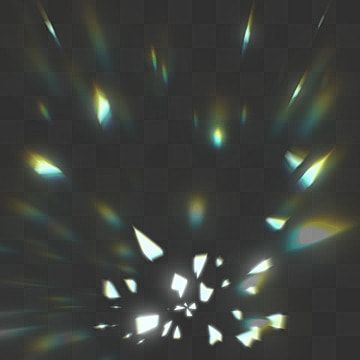 Figure 13
I figured out a way to do that by projecting a generated cube map onto the other objects. According to LearnOpenGL [3] this technique is sometimes used by engines to make shadows using a shadow map.
I’m going to start of this explanation in 2D, as it’s easier to visualize what happens that way. I’ll also use an icosphere instead of the chandelier, as that makes it easier to see what’s supposed to happen.
First of let’s establish the goal: I want the light to be refracted onto different objects, in a way that looks similar to figure 13, as accurate as possible, without using raytracing, as that’s way too heavy to use. In 2D, ideally the end result would look something like figure 14.
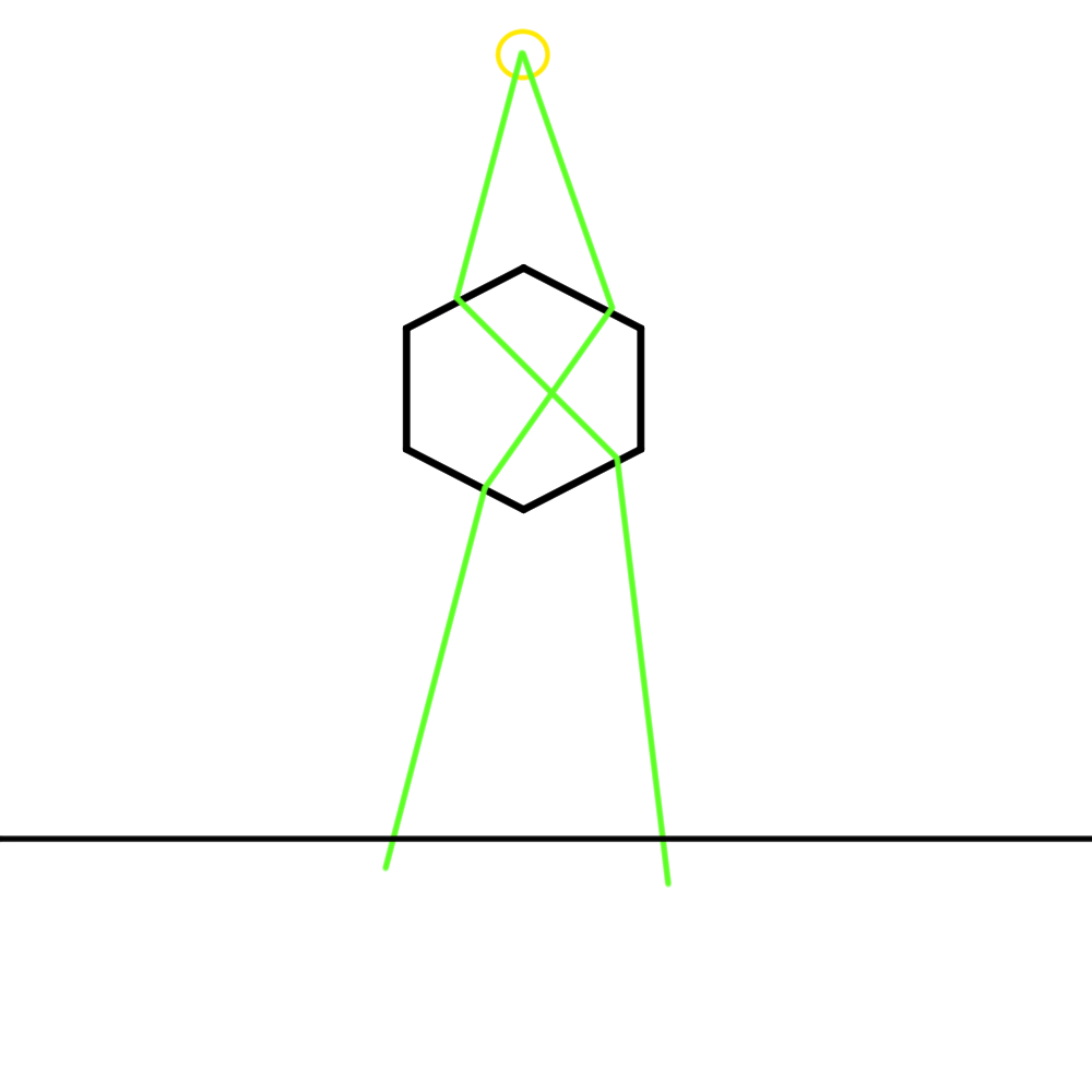 Figure 14
Where the yellow circle is the light source, and the green lines are the way the light should be refracted. Note that this isn’t exact, it’s just a sketch to show the intention.
Since this will add a lot of math to just the rays, that could make it difficult to see if the cube map and/or projection is actually working correctly, we’re first going to do this with the face normals instead, which would look something like figure 15.
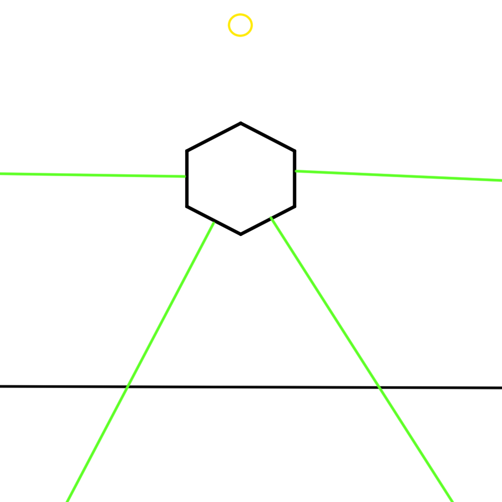 Figure 15
First thing we’re going to do with this, is make a cube around the object, that can be used to draw the dots on. Please note that this cube doesn’t actually exist. It’s not a real object in the scene. It’s just something that’s used in code to draw the dots on. To help understand the logic however, I am going to draw it into the example image, as that does make it easier to see what’s happening.
Now we need to make images within code, and draw dots on them anywhere the rays and the cube intersect. In code, this means finding the face normal, checking the absolute value of the normal to see which axis has the biggest number and checking whether the normal is positive or negative (as this will determine what side the dot should be drawn on). Once we know the correct side we can take the other two values in the normal to determine where on the image the dot should be placed. I’m only going to show the code for one side as it’s a bit repetitive, but this is the idea:
if entryNorm.x > entryNorm.y and entryNorm.x > entryNorm.z:
			if N.x > 0:
				if N.y < 0 && N.z <0:
					draw_circle(imgRight, Vector2(512-entryNorm.z*512,512+entryNorm.y*512), 5, Color.ALICE_BLUE)
				elif N.y < 0:
					draw_circle(imgRight, Vector2(entryNorm.z*512+512,512+entryNorm.y*512), 5, Color.ALICE_BLUE)
				elif N.z < 0:
					draw_circle(imgRight, Vector2(512-entryNorm.z*512,-entryNorm.y*512+512), 5, Color.ALICE_BLUE)
				else:
					draw_circle(imgRight, Vector2(entryNorm.z*512+512,-entryNorm.y*512+512), 5, Color.ALICE_BLUE)
				print("+x")
			else:
				if N.y < 0 && N.z <0:
					draw_circle(imgCube, Vector2(512-entryNorm.z*512,512+entryNorm.y*512), 5, Color.ALICE_BLUE)
				elif N.y < 0:
					draw_circle(imgCube, Vector2(entryNorm.z*512+512,512+entryNorm.y*512), 5, Color.ALICE_BLUE)
				elif N.z < 0:
					draw_circle(imgCube, Vector2(512-entryNorm.z*512,-entryNorm.y*512+512+), 5, Color.ALICE_BLUE)
				else:
					draw_circle(imgCube, Vector2(entryNorm.z*512+512,-entryNorm.y*512+512), 5, Color.ALICE_BLUE)
				print("-x")
This leads to the following images seen in figure 16. It’s a bit difficult to see, but these images show white dots generated on each face.
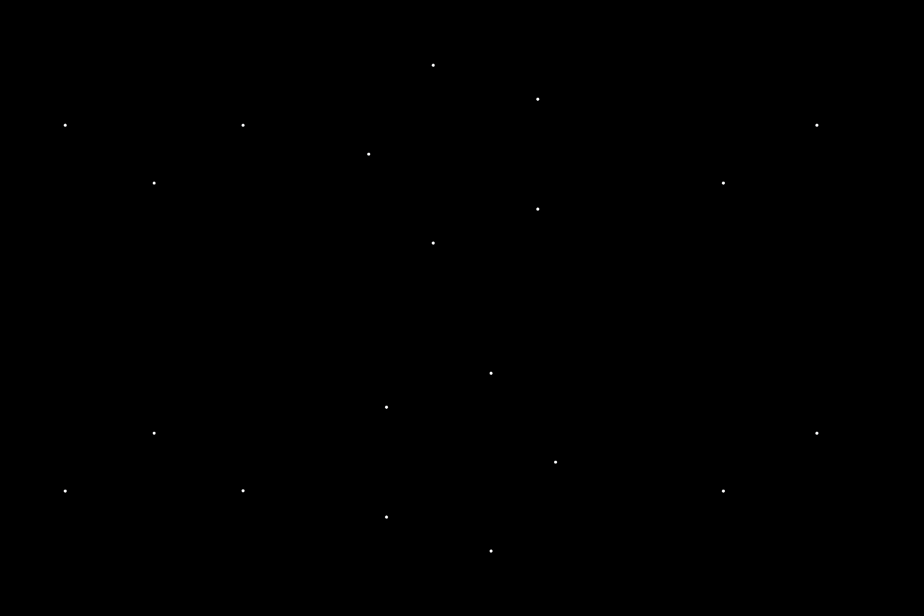 Figure 16
Now that the cube map is generated, that still needs to be projected onto the other objects in the scene. Let’s start off with the floor. On the floor 5 out of 6 generated images should be rendered (in 2D 3 out of 4). The only image left out would be the top of the box, the +y side.
What should be rendered on the floor is the following (fig. 17), with purple being the -Y side, green and blue being the -X and +x side, and pink and red being the +z and -z sides.
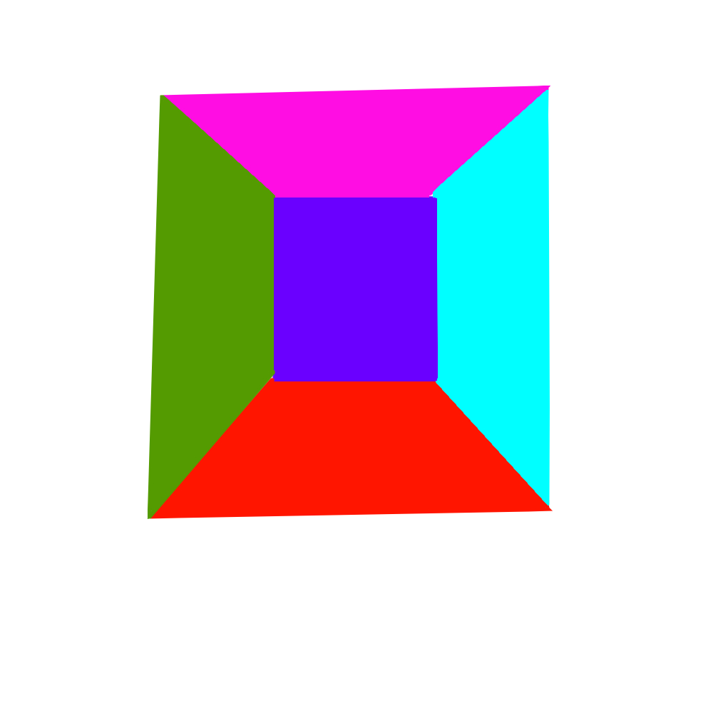 Figure 17
Since the -Y (purple) side is the most straight forward, let’s start off with that. If we draw a line from the center of the light source to the edge of the bottom side of the imaginary cube, and continue that line to the floor, we should find the start and end position of the image on the floor as seen in figure 18.
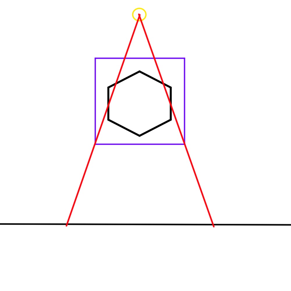 Figure 18
Now, how do we do that? Math. We know the position of our light source, the position of the imaginary cube, and the position of the floor, based on that, we can figure this out.
Let’s say the light source is at (0.0, 2.0, 0.0). The bottom face of the cube is 2x2 with the center drawn at (0.0,-1.0,0.0). Lastly the floor, for which only really the y value matters is at -2.0.
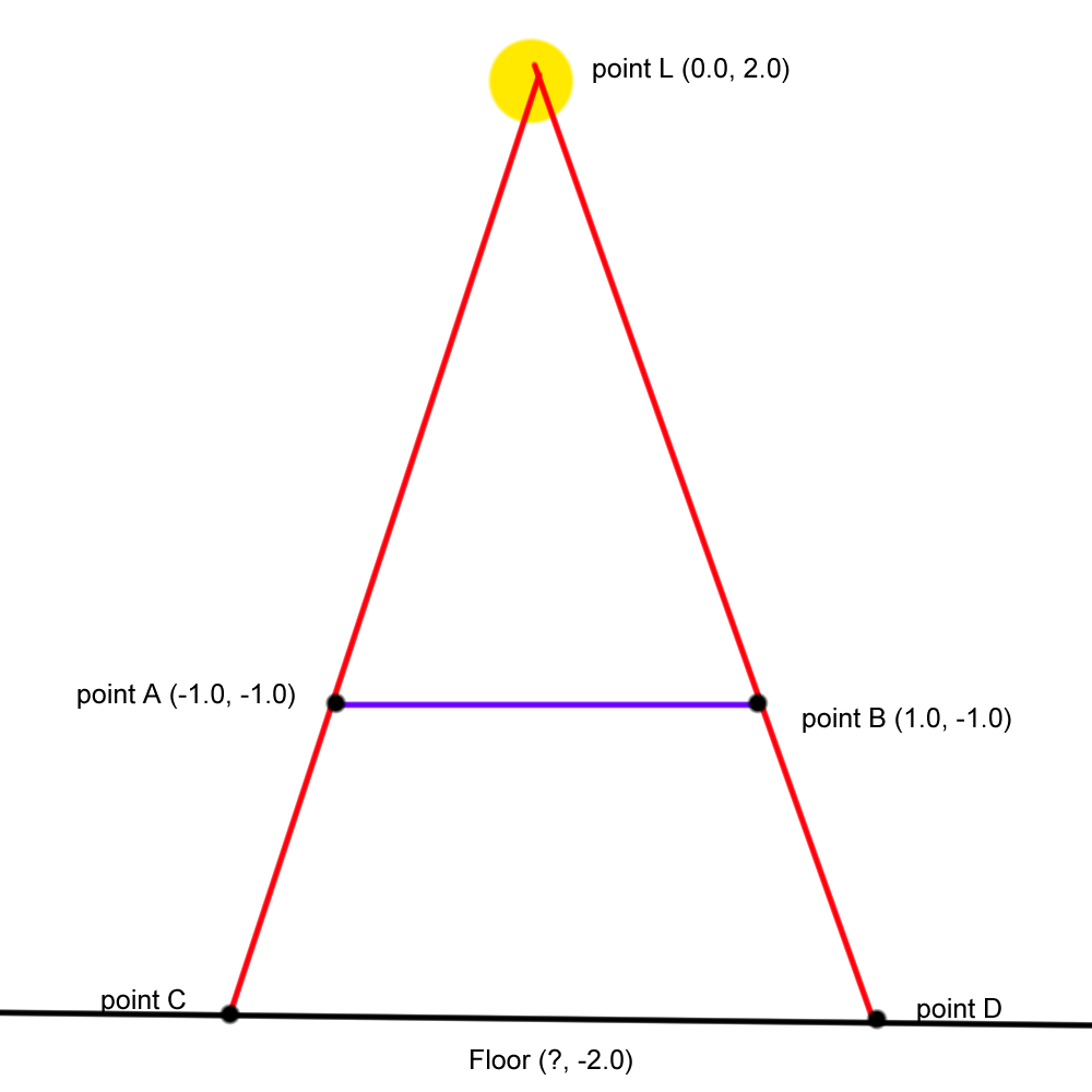 Figure 19
Let’s draw a line from point L to the floor. We know line LF = 4, line LE = 3, line EF = 1, and the angles between the new line and the cube line, and the new line and the floor line are 90 degrees. The halves of the cube line are both 1.
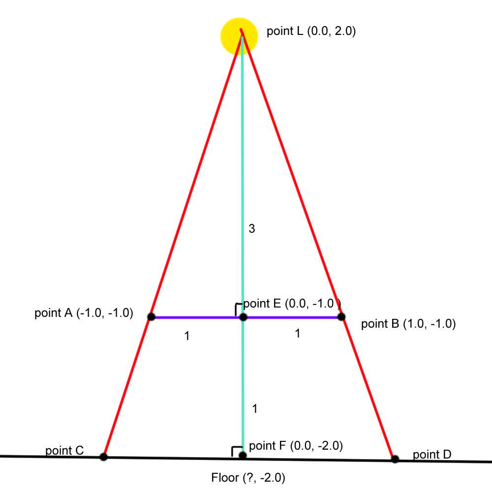 Figure 20
Based on that info we can calculate the remaining 3 unknowns for triangle LEB (which is the same as LEA but mirrored).
Side LB: a^2 + b^2 = c^2 → sqrt(3^2 + 1^2) = 3.162
Angle L: acos((a^2 + b^2 - c^2)/2ab) → acos((3.162^2 + 3^2 - 1^2)/23.1623) = 18.435
Angle B: acos((a^2 + c^2 - b^2)/2ac) → acos((3.162^2 + 1^2 - 3^2)/23.1621) = 71.565
Since triangle LFD is the same but bigger, the angles will remain the same, meaning that angle D = 71.565.
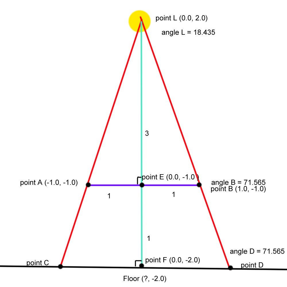 Figure 21
Now we also have enough values to calculate for the remainder of LFD.
Side LD = b·sin(A)/sin(B) → 4*sin(90)/sin(71.565)= 4.21637
Side FD = b·sin(C)/sin(B) → 4*sin(18.435)/sin(71.565) = 1.33334
Since point D has to have the same Y as point F, this means point D = (F+1.33334, F) = (1.33334, -2.0) and point C = (F-1.33334, F) = (-1.33334, -2.0)
These same numbers would work in 3D:
upper left = (F-1.33334, F, F+1.33334)
lower left = (F-1.33334, F, F-1.33334)
upper right = (F+1.33334, F, F+1.33334)
lower right = (F+1.33334, F, F-1.33334)
Based on these numbers we can check in code whether the current world coordinate of the fragment is within this square, and if so, map the bottom texture on it, which for this side is easy, as it’s just a simple square:
if(world.x > -FD && world.x < FD && world.z > -FD && world.z < FD){

			vec2 uv = world.xz/FD;
			uv = uv * 0.5 +0.5;
			ALBEDO += texture(bottomTex, uv).xyz;
			EMISSION += texture(bottomTex, uv).xyz
		}
Let’s move on to the +X side. Thing get a bit trickier here, as it’s no longer a simple square we need to draw. In this case, we need to draw a ray from the light source to the top edge of the sides of the imaginary cube, and draw that out to the floor as seen in figure 22.
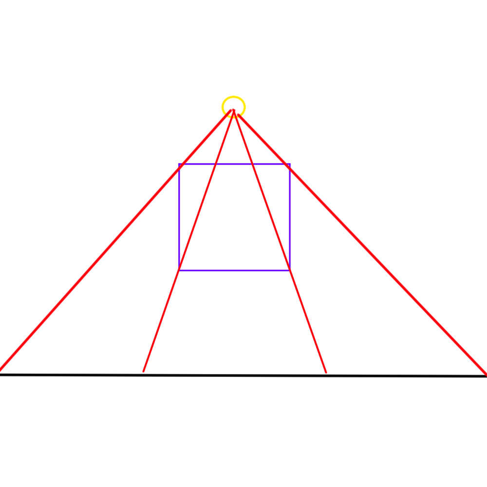 Figure 22
We have obtained two new points and 2 new triangles: point G at (1.0,1.0) and point H at (?,-2.0).
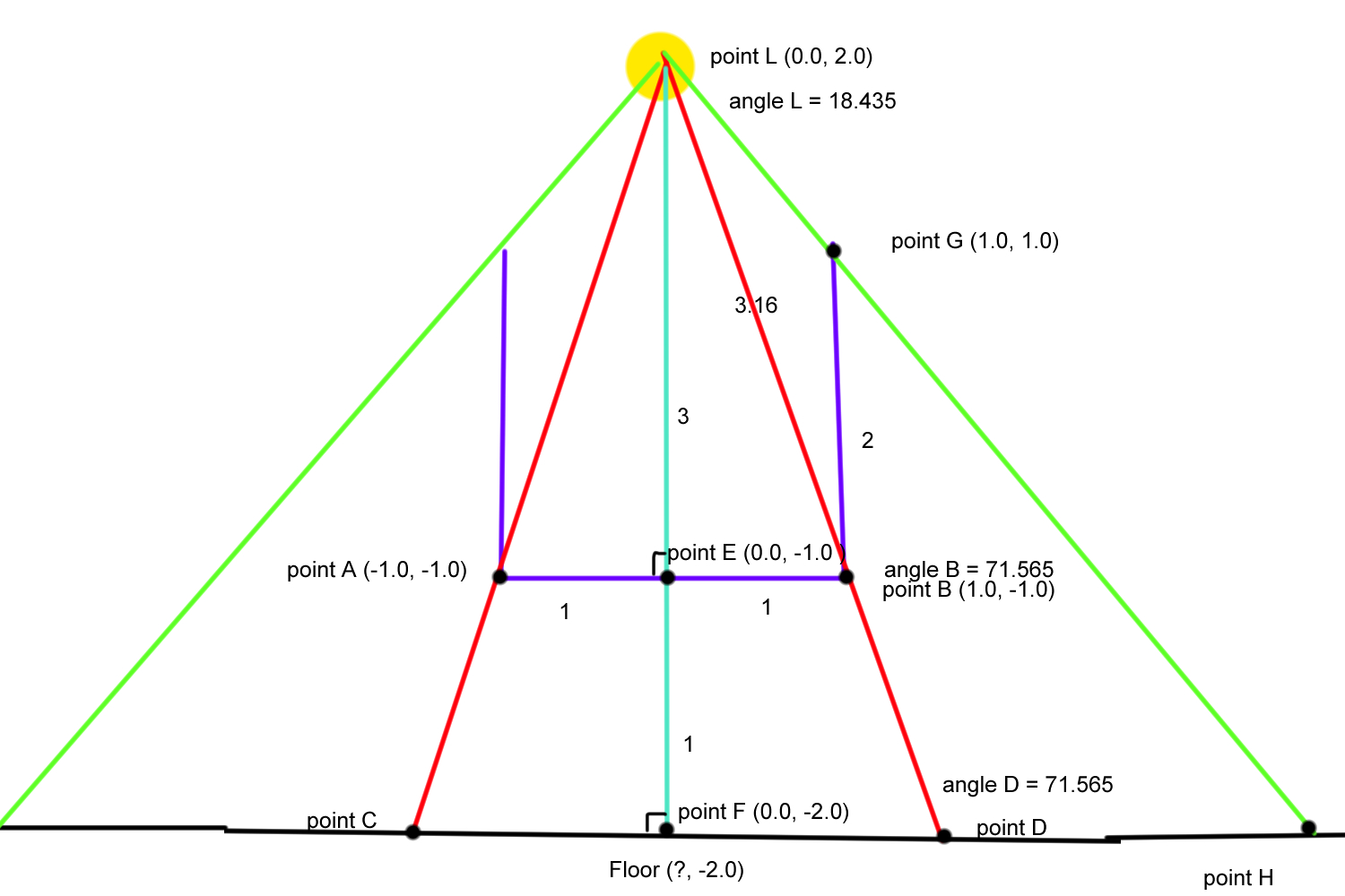 Figure 23
First we’ll focus on triangle LBG. We can calculate angle B in LBG by doing 90 - angle B in LEB = 90-71.565 = 18.435.
Now we have 3 knowns again, so we can find the 3 unknowns:
side LG = sqrt(b^2 + c^2 - 2bccos(A)) → sqrt(3.162^2+ 2^2 -23.1622cos(18.435)) = 1.414
angle L = acos((a^2 + b^2 - c^2)/2ab) → acos((1.414^2 + 3.162^2 - 2^2)/21.4143.162) = 26.57
angle G = acos((a^2 + c^2 - b^2)/2ac) → acos((1.414^2 + 2^2 - 3.162^2)/21.4142) = 134.995
We also know that angle D in LDH = 180 - angle D in LFD = 180 -71.565 =108.435
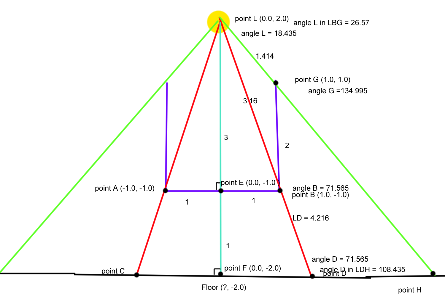 Figure 24
We now know three values in LDH, which means we can calculate the other three:
angle H = 180 - A - B → 180 - 108.435 -26.57 = 44.5995
side LH = b·sin(A)/sin(B) → 4.216*sin(108.435)/sin(44.995) = 5.65685
side DH = b·sin(C)/sin(B) → 4.216*sin(26.57)/sin(44.995) = 2.66713
Which means that point H = (F.x + FD +DH, F.y)
That means the Y value for our uv should be mapped between F.x+FD and F.x + FD +DH. Now if we were to implement that in the same way, we’d get the top view seen in figure 25.
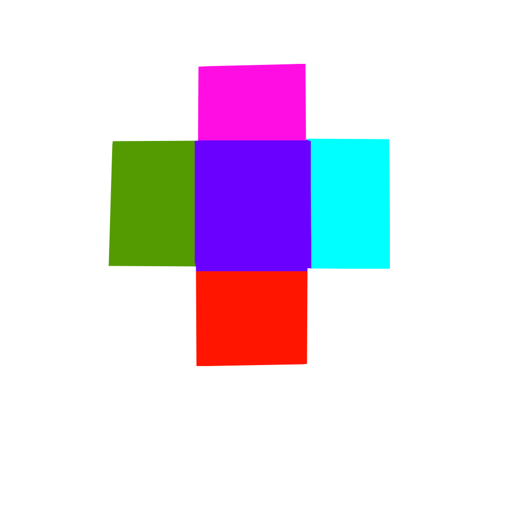 Figure 25
Because of this we need to use Bay centric coordinates [4] to check for the points in the triangles that should appear on the sides of each of these squares as well. In code that looks like this:
else if(world.x < DH+FD && world.x > FD && world.z > -FD && world.z < FD ||
		point_in_triangle(world.xz, vec2(FD, FD), vec2(FD+DH, FD), vec2(FD+DH, FD+DH))||
		point_in_triangle(world.xz, vec2(FD, -FD), vec2(FD+DH, -FD), vec2(FD+DH, -FD-DH))){
			vec2 uv = world.zx;
			uv.y = (world.x - FD)/(DH);
			uv.x = uv.x / (0.95+(((FD/2.0 +DH)-1.0)*uv.y));
			uv.x = (uv.x - (-FD/2.0))/(((-FD/2.0)+ DH)-(-FD/2.0))+0.235;
			uv.x = uv.x*-1.0;


			ALBEDO += texture(leftTex, uv).xyz;
			EMISSION += texture(leftTex, uv).xyz;
	}
All of this ends up looking like figure 26. Note, the textures are different to make it more visible what’s happening.
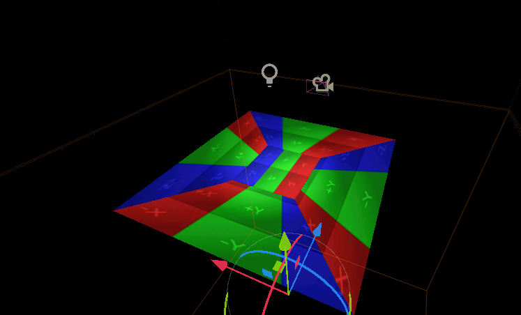 Figure 26
What we have so far works great, but only on flat surfaces. In reality, walls and objects exist. So, we also need to figure out a way to do the sides correctly, and not stretched out as can be seen in figure 27.
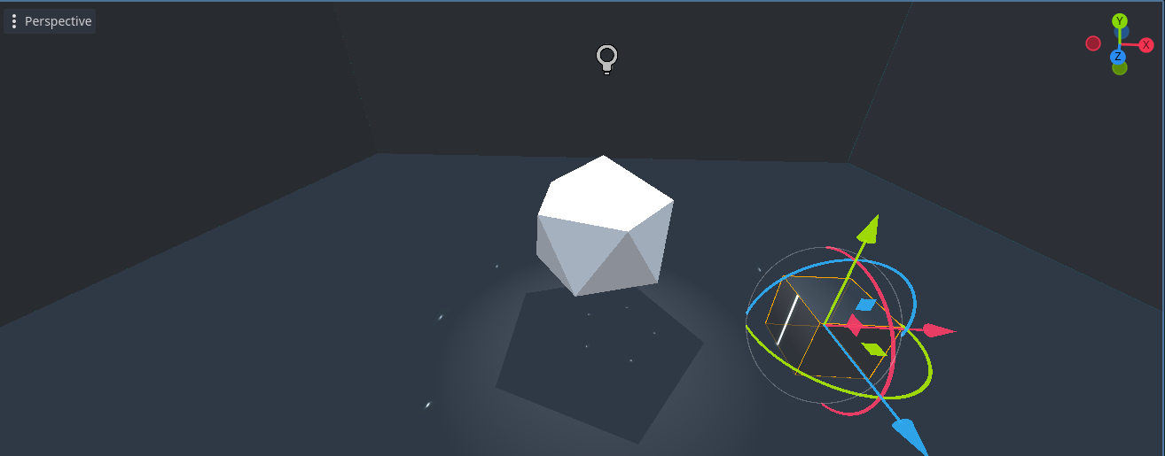 Figure 27
After fixing the sides by adding that in with the math, it looks like figure 28.
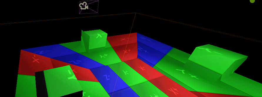 Figure 28
The image is now essentially folded around the box, using it’s position to know from where to start. This results in only the left and right side of the box looking slightly warped, but this is also usually the case for real shadows. One “bug” this setup has, is that you’d expect the projection on the floor to disappear behind the boxes. This is rather complex, as this is all done in a shader, meaning the floor doesn’t know where the boxes are.
I added some eclipses in red green and blue behind each of the white dots generated earlier, in order to give it a bit more of that dispersed light effect. This can be seen in figure 29.
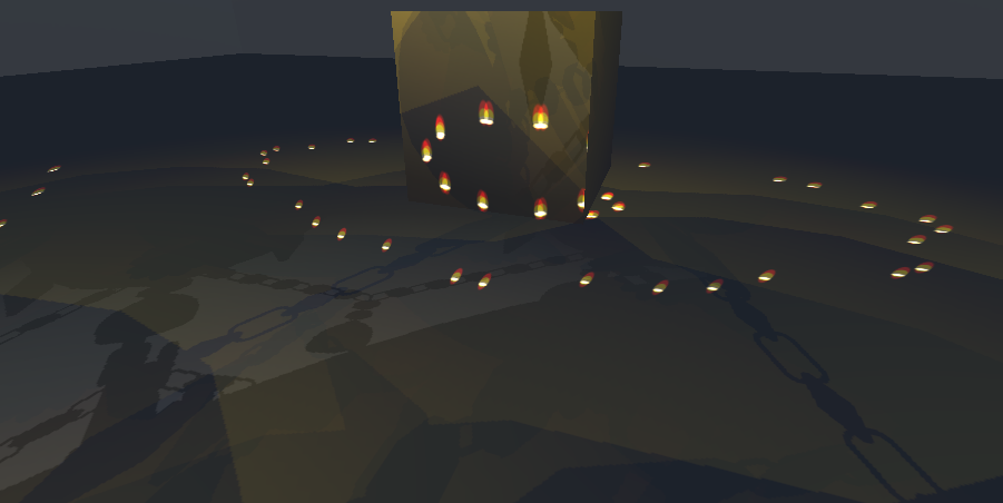 Figure 29
The final result can be seen in figure 30.
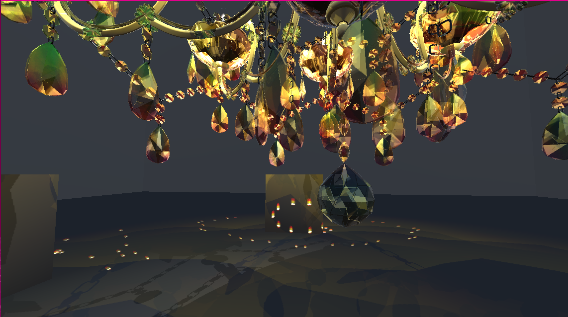 Figure 30
Performance
The visual profiler(fig. 31) shows no significant performance spikes. The initial high part is caused by the way Godot loads in shadows, this isn’t caused by anything I made.
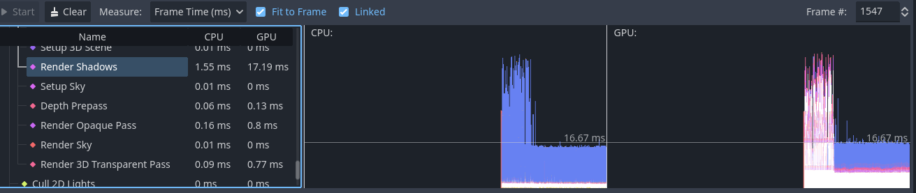 Figure 31
Conclusion
The final result can be seen in figure 32. This is very performant, but not as real time as I had hoped. When the chandelier moves, the refraction on the ground doesn’t move along, because regenerating the cube maps is very heavy. A potential fix for this might be to not fully regenerate them, but only slightly displace them upon movement.
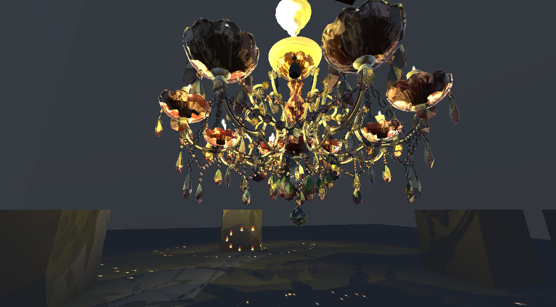 Figure 32
The generated images could also be more realistic, perhaps with some randomness to them, as it currently looks too symmetrical and neat. This could potentially be fixed by using crystal morphology [5], from my research I learned that there might be a way to calculate that sort of pattern with Laue equations [6], but this is a little too complicated to make within a couple weeks.
Another problem is the refraction on the floor is rendered on the full projected space, including behind the cubes, where there shouldn’t be refraction visible, as the projection would be blocked by the cube.
Within the base of the chandelier, I use both fake reflection and fake refraction, neither work fully according to physics, which makes it more performant, but slightly less realistic. This was a choice I made early on, as I think it’s more important for immersion to not have any kind of lag or performance drops than it is to be 100% fully realistic.
The model used in this wasn’t made by me, but one I found online. It looks great, but the UV map is a mess, which means the normal map doesn’t work quite the way it should. If it would work correctly the refraction would look way better, which I know, because I tried on a separate object, but fixing the UV for an object this big and detailed is going to take a while, meaning I can’t do that with the current time constraints.
Besides the aforementioned fixes, to expand on this chandelier, some other things to look at would be:
- A way to make it possible for the chandelier to move without mismatching with the refraction on the floor.
- Smoke coming from the candles when blown out.
Sources
[1] “LearnOpenGL - Coordinate Systems.” https://learnopengl.com/Getting-started/Coordinate-Systems
[2] “Standard material 3D and ORM material 3D,” Godot Engine Documentation. https://docs.godotengine.org/cs/4.x/tutorials/3d/standard_material_3d.html
[3] “LearnOpenGL - Shadow Mapping.” https://learnopengl.com/Advanced-Lighting/Shadows/Shadow-Mapping
[4] Wikipedia contributors, “Barycentric coordinate system,” Wikipedia, Oct. 30, 2024. https://en.wikipedia.org/wiki/Barycentric_coordinate_system
[5] P. Gajjar et al., “Crystallographic tomography and molecular modelling of structured organic polycrystalline powders,” CrystEngComm, vol. 23, no. 13, pp. 2520–2531, Jan. 2021, doi: 10.1039/d0ce01712d.
[6] Wikipedia contributors, “Laue equations,” Wikipedia, Feb. 11, 2024. https://en.wikipedia.org/wiki/Laue_equations
[fig. 1] N. Hays, “Image of refracted light,” Pinterest, Jun. 19, 2023. https://in.pinterest.com/pin/refraction-of-light-white-transparent-rainbow-refracted-light-effect-of-crystal-glass-diamond-light-spot-refraction-rainbow-png-image-for-free-download--534872893259082588/
[fig. 10] E. RealEstate, “Guidelines to select the perfect chandelier,” ETRealty.com | Lighting, Nov. 18, 2019. [Online]. Available: https://realty.economictimes.indiatimes.com/news/lighting/indoor-lighting/guidelines-to-select-the-perfect-chandelier/72101704