Introduction
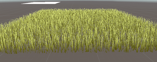
Grass might seem like a small detail, but it adds a lot to how a game looks and feels. It makes the game world seem more real and alive. A good, realistic landscape also helps make the game feel more immersive. Unity has his own build in grass drawing using flat 2D images to add grass to the ground, but these often look fake and don’t move. Adding too many of them can also slow down the game and lower the frame rate.
Because of this, I wanted to learn how to make a custom grass shader that would still work with Unity’s terrain tools. A shader like this would let me create grass that looks more realistic, with effects like swaying in the wind. Using Unity’s terrain system with my own shader would allow me to create a unique look.
Problem statement
Shaders play a vital role in game performance, particularly in expansive, grassy areas where many elements need to be rendered simultaneously. To maintain high frame rates, it’s essential to optimize shaders so they only remain active near the player, minimizing unnecessary rendering in distant areas. This grass shader adapts dynamically to the player’s surroundings, boosting performance by concentrating resources exactly where they’re needed.
Another challenge lies in Unity’s terrain system. A key benefit of using terrains is the ability to layer multiple textures, which creates a more detailed and varied landscape. However, many custom shaders aren’t compatible with these terrain features, limiting functionality. This article will walk through the process of creating a custom grass shader that not only supports Unity’s terrain features but also allows for dynamic grass rendering and layered textures delivering a realistic and optimized gaming environment.
Research question
How can a grass shader be developed that incorporates terrain features while maintaining strong performance?
- How can a grass shader be integrated with Unity’s terrain system while preserving its core functionalities?
- What optimizations can be implemented in the shader to prevent performance issues when rendering realistic grass?
How to make a grass shader
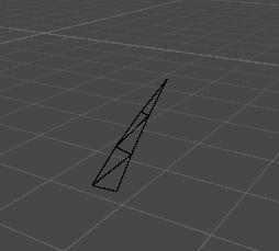
To create grass in a shader, multiple triangles are used because they provide a shape that resembles grass more effectively than other forms. Initially, I considered using simple lines and coloring them to represent grass. However, lines are too flat, as they only have two points, point A, which sits on the ground, and point B, which defines the height. This approach lacked the depth and dimensionality needed for realistic grass.
After reviewing some reference images, I discovered that triangles are the most suitable shape for creating grass. In this shader, each triangle is divided into multiple sections, allowing for bending and movement, which gives the grass a more lifelike appearance.
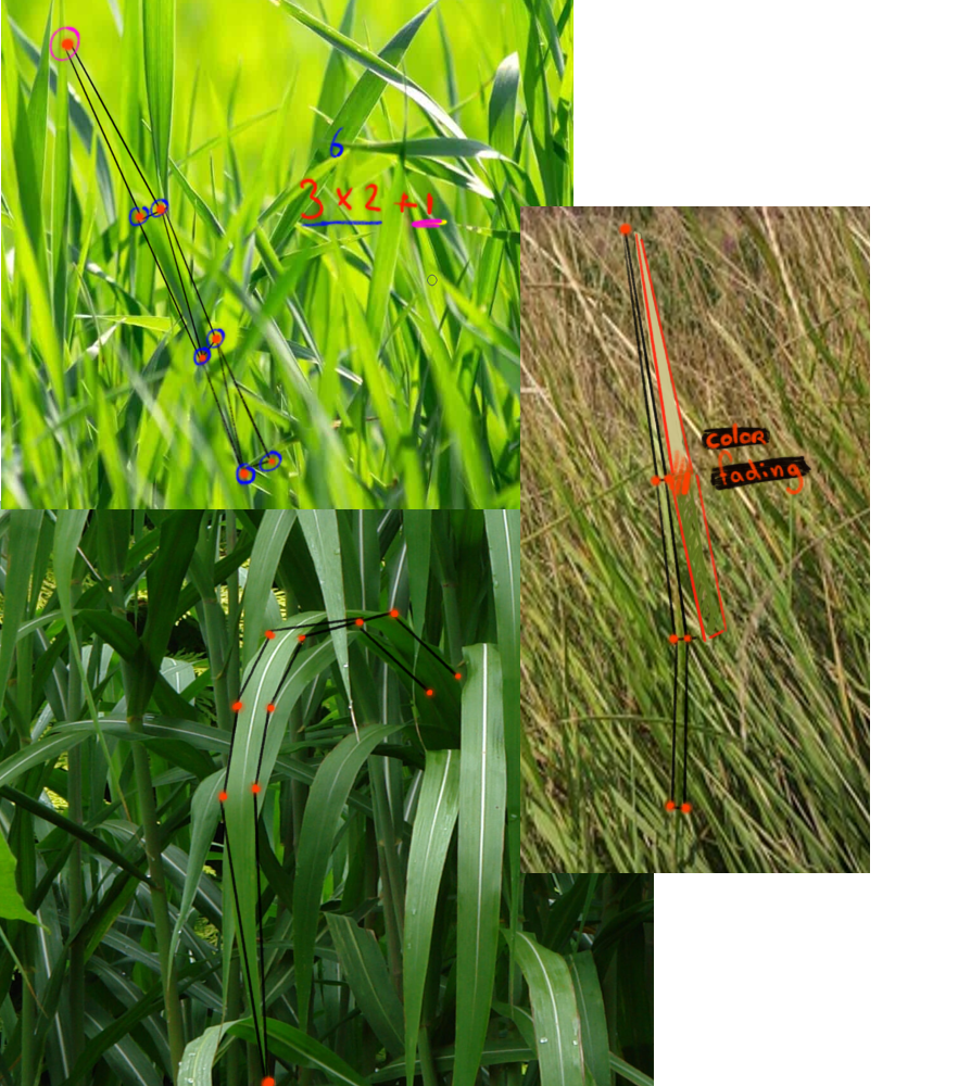
The image showed that grass appeared most realistic when it could bend naturally. Since grass comes in many colors and shapes, it was important to design this shader with highly adjustable variables to capture a range of appearances. The grass is represented by stacked rectangles, each made up of two triangles, totaling four unique vertices. These four vertices form a quad. I use one quad for the bottom, one for the middle, and a single triangle at the top to create the grass tip.
The grass color was also designed to fade, allowing for variations like dark green to light green, yellow, or even fully yellow. This shader was created to offer flexibility, making it adaptable to virtually any type of grass you can imagine.
Before drawing any grass, it’s best to subdivide the placement areas. This ensures that the grass appears across multiple locations rather than being concentrated on a single vertex of the mesh. This subdivision process is handled using a cginc file, which helps keep the shader organized and maintainable.
Cginc files
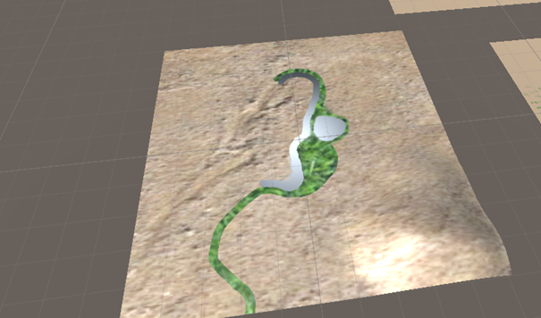
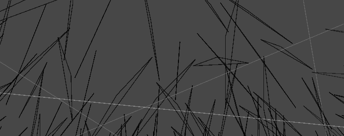
Cginc files are used for shaders that share the same functions. To render grass, it’s necessary to subdivide the areas where the grass will appear. This increases the number of vertices in the terrain mesh. In the first image, grass is rendered on a single vertex, whereas in the second image, the areas are subdivided to allow more instances of grass to be drawn. 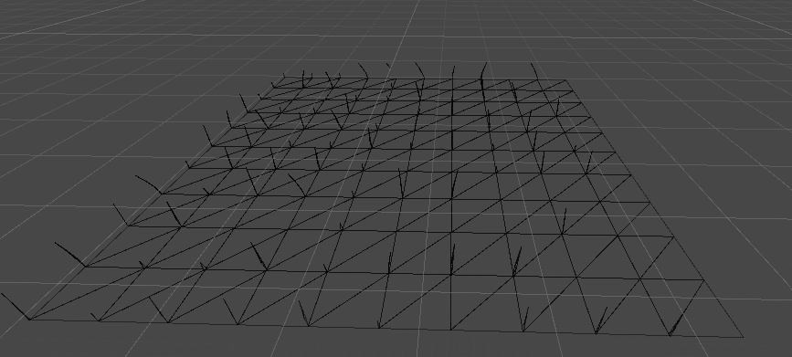
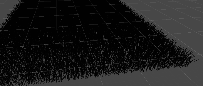
The .cginc file is used for this purpose. In the .cginc file, the tiles visible in the first image represent additional positions where grass can be placed. Grass can only be rendered within a defined tessellated triangle patch, meaning it cannot appear outside of this area. These tessellated triangle patches are defined using triangles.
TessellationFactors patchConstantFunction (InputPatch<vertexInput, 3> patch)
{
	TessellationFactors f;
	f.edge[0] = _TessellationUniform;
	f.edge[1] = _TessellationUniform;
	f.edge[2] = _TessellationUniform;
	f.inside = _TessellationUniform;
	return f;
}
This part of the code determines the edges of the triangle and defines what is meant to be inside the triangle. The vertexInput ends with 3, as a triangle has 3 points.
vertexOutput domain(TessellationFactors factors, OutputPatch<vertexInput, 3> patch, float3 barycentricCoordinates : SV_DomainLocation)
{
    vertexInput v;

    #define MY_DOMAIN_PROGRAM_INTERPOLATE(fieldName) v.fieldName = \
        patch[0].fieldName * barycentricCoordinates.x + \
        patch[1].fieldName * barycentricCoordinates.y + \
        patch[2].fieldName * barycentricCoordinates.z;

    MY_DOMAIN_PROGRAM_INTERPOLATE(vertex)
    MY_DOMAIN_PROGRAM_INTERPOLATE(normal)
    MY_DOMAIN_PROGRAM_INTERPOLATE(tangent)

    return tessVert(v);
}
In this section, a calculation is using the vertex points of the triangles. This calculation determines where a patch of grass can be placed.
Once the Cginc file is created, it is important to reference it in the active shader. This is accomplished by calling it as follows:
#Include "MapTheCGINCisIn/fileName.fileType"
When including a file, it’s important to specify the correct path.
Randomness
To create more randomness, a random generator produces a number between 0 and 1. This allows for the generation of random heights and widths in the shader, resulting in a more natural appearance. Since there is no built-in function available to randomly generate a number, it is necessary to create a custom function for this purpose.
float GetRandomFloat(float3 co)
{
    return frac(sin(dot(co.xyz, float3(12.9898, 78.233, 53.539))) * 43758.5453);
}
A rotation matrix is also used to rotate the triangles, making each blade of grass more unique. By providing an angle and an axis, the matrix can generate the necessary rotation. Although the rotation is hardcoded, random floats can be applied to introduce variations, creating random rotations for a more natural appearance. This rotation matrix also plays a role in simulating the bending of the grass, further enhancing realism.
float3x3 AngleAxis3x3(float angle, float3 axis)
{
    float c, s;
    sincos(angle, s, c);

    float t = 1 - c;
    float x = axis.x;
    float y = axis.y;
    float z = axis.z;

    return float3x3(
        t * x * x + c, t * x * y - s * z, t * x * z + s * y,
        t * x * y + s * z, t * y * y + c, t * y * z - s * x,
        t * x * z - s * y, t * y * z + s * x, t * z * z + c
        );
}
Drawing grass
After that, the GeometryOutput is created. This determines the size of a triangle and the placement of the grass. Since the shader surrounds the player, it is important for it to be close to the player, so the world position must also be considered. Therefore, the calculation of how far the player is in the world and where the player is positioned in relation to the world position is essential.
To create the triangles, a function from the .cginc file is called. This function generates positions, normals, and ensures the use of a VertexOutput structure. In the VertexOutput, all necessary values are translated from vertex to geometryOutput and interconnected: the position is mapped to the position, the normal to the normal, and so on.
geometryOutput GenerateGrassVertex(float3 vertexPosition, float width, float height, float forward, float2 uv, float3x3 transformMatrtix)
           {
               float3 tangentPoint = float3(width, forward, height);

               float3 tangentNormal = normalize(float3(0, -1, forward));

               float3 localPosition = vertexPosition + mul(transformMatrtix, tangentPoint);
               float3 localNormal = mul(transformMatrtix, tangentNormal);

               return VertexOutput(localPosition, localNormal, uv);
           }
To effectively render the grass, a function called void geo is used. Within this function, a triangle, which is connected to the vertexOutput, is defined. The triangleStream then positions the vertices to form the triangles that make up the grass blades.
#define BLADE_SEGMENTS 3

[maxvertexcount(BLADE_SEGMENTS * 2 + 1)]
void geo(triangle vertexOutput IN[3], inout TriangleStream<geometryOutput> triStream)
           {

           }
The BLADE_SEGMENTS ensure that the grass is defined in parts. This is useful for bending the grass.
The BLADE_SEGMENTS operate by calling the vertices. There are three parts: the beginning of the segments, which has two vertices, and the last part, which is the tip of the grass and ends with one vertex.
To create the bending of the triangle, the rotation matrix defined earlier is utilized. To introduce randomness, the GetRandomFloat function is invoked, which performs calculations using the position, π and a float value of 3, representing the axis. The same approach applies to the bendRotationMatrix.
float3 pos = IN[0].vertex.xyz;

float3x3 facingRotationMatrix = AngleAxis3x3(GetRandomFloat(pos) * UNITY_TWO_PI, float3(0, 0, 1));
float3x3 bendRoationMatrix = AngleAxis3x3(GetRandomFloat(pos.zzx) * _BendRotationRandom * UNITY_PI * 0.5, float3(-1, 0, 0));
An UV map is used for the wind. The XYZW values from the UV map are utilized to calculate the intensity and direction of the wind. The strength and frequency can be adjusted in the inspector.
float2 uv = pos.xz * _WindDistortionMap_ST.xy + _WindDistortionMap_ST.zw + _WindFrequency * _Time.y;
float2 windSample = (tex2Dlod(_WindDistortionMap, float4(uv, 0, 0)).xy * 2 - 1) * _WindStrength;
float3 wind = normalize(float3(windSample.x, windSample.y, 0));

float3x3 windRotation = AngleAxis3x3(UNITY_PI * windSample, wind);
Move the shader with the player
An additional script is used to link the shader with the player’s position, transferring the necessary information to the shader. In the script, a string is utilized to reference the variable intended to be updated with the player’s position, establishing the connection between them.
void Update()
{
    grassMaterial.SetVector("_PlayerPosition", new Vector3 (player.position.x,0,player.position.z));
}
The function calculates the distance from the player to a specific radius that can be changed in the inspector, creating a circle around the player that is filled with grass.
float dis = distance(WorldPos, _PlayerPosition.xyz);

float innerFadeStart = _Radius- _Radius * _FadeAmount;
float innerMask = smmoothstep(innerFadeStart, _Radius, dis);
To let this react to the grass it needs to get called in the position of the grass. Because the grass is split in 3 this needs to get called in all the 3 times called grass parts.
triStream.Append(GenerateGrassVertex(pos/ innerMask, segmentWidth, segmentForward, float2(0,t), transformMatrix));
triStream.Append(GenerateGrassVertex(pos/ innerMask, -segmentWidth, segmentForward, float2(1,t), transformMatrix));
This is called in the for loop of the grassblades. The defined of the position with the innermask makes sure that the grassblades only get called around the player.
https://www.youtube.com/watch?v=xmq9nhYKUYM
Terrain shader
The terrain utilizes a surface shader that employs different base colors, with this shader a color gets linking to a specific texture. This connection is evident in the images provided. The first image displays the colors applied to the terrain, while the second illustrates the same terrain with textures applied.

To achieve this, a surface shader is created. A line of code is added to the properties to ensure that everything functions like a terrain layer. The first layer is for textures, while the second is for the normal map.
[HideInInspector] _Control("Control (RGBA)", 2D) = "red" {}

[HideInInspector] _Splat3("Layer 3 (A)", 2D) = "white" {}
[HideInInspector] _Splat2("Layer 2 (B)", 2D) = "white" {}
[HideInInspector] _Splat1("Layer 1 (G)", 2D) = "white" {}
[HideInInspector] _Splat0("Layer 0 (R)", 2D) = "white" {}

[HideInInspector] _Normal3("Normal 3 (A)", 2D) = "bump" {}
[HideInInspector] _Normal2("Normal 2 (B)", 2D) = "bump" {}
[HideInInspector] _Normal1("Normal 1 (G)", 2D) = "bump" {}
[HideInInspector] _Normal0("Normal 0 (R)", 2D) = "bump" {}
There is a section in the inspector dedicated to assigning different layers within the shader, allowing the use of multiple color maps. Only four colors are available, which means a maximum of four layers with textures can be applied. This limitation exists because there are four basic colors: Red, Blue, Green, and Alpha.
To link the colors with the layers, each layer is multiplied by a corresponding color.
fixed4 c = tex2D (_Control, IN.uv_Control) * _Color;
fixed4 s0 = tex2D(_Splat0, IN.uv_Control) * _Color;
fixed4 s1 = tex2D(_Splat1, IN.uv_Control) * _Color;
fixed4 s2 = tex2D(_Splat2, IN.uv_Control) * _Color;
fixed4 s3 = tex2D(_Splat3, IN.uv_Control) * _Color;

o.Albedo = s0 * c.r + s1 * c.g + s2 * c.b + s3 * c.a ;
The tex2D is linked to the uv_Control, which defines the color positions on the terrain. In the tex2D function, the front part specifies the texture based on the intended area. This texture data is then multiplied by the color information stored in the variable c, which contains detailed data about the terrain.
Connecting the grass with terrain shader
The current issue is that a unlit shader can not be directly connected to an surface shader. There are several ways to work around this limitation. One option is to use only an unlit shader by converting the surface shader into an unlit shader. Alternatively, a custom .cginc file can be created to integrate specific functions for the unlit grass shader. For now, the surface shader is being converted to an unlit shader and used as an additional part of the overall shader. It’s even possible to reference the surface shader within the unlit shader through direct calls.
I chose to convert the surface shader into an unlit shader. Since lighting calculations from the surface shader were not essential for my needs, I found that an unlit shader offered more flexibility for customization.
How does the terrain work with layers
Before diving into shader development, it’s important to understand how terrain works in Unity. When a terrain is created, a new file is generated to store all the terrain’s information, including texture layers and color data.
When adding texture layers to a terrain, Unity first marks specific areas with base colors, which are defined and stored in the terrain file. In the shader, these base colors are then used to blend with the tex2D texture, which defines the texture itself and its UV coordinates. This process ensures that the texture aligns correctly with the color-marked areas on the terrain.
Surface shader
To convert a surface shader into an unlit shader, a few lines need to be removed.
#pragma surface surf Standard fullforwardshadows
This is the first line that defines a surface shader. The shader written can utilize different functions from this pragma. The biggest different from unlit and surface shader is that a surface shader calculate light in a particular way and in an unlit shader this has to be done by coding it in the shader.
The void function connects the color drawn on the terrain with a texture.
void surf (Input IN, inout SurfaceOutputStandard o)
       {
         fixed4 c = tex2D (_Control, IN.uv_Control) * _Color;
         fixed4 s0 = tex2D(_Splat0, IN.uv_Control) * _Color;
         fixed4 s1 = tex2D(_Splat1, IN.uv_Control) * _Color;
         fixed4 s2 = tex2D(_Splat2, IN.uv_Control) * _Color;
         fixed4 s3 = tex2D(_Splat3, IN.uv_Control) * _Color;

         o.Albedo = s0 * c.r + s1 * c.g + s2 * c.b + s3 * c.a ;
       }
When this code is placed in the void function, an error appears on the screen if the #pragma directive is removed. This is because SurfaceOutputStandard relies on #pragma to define it as a surface shader. To fix this issue, the function can be modified to return a fixed4 type, which is used for handling colors.
The fixed4 type consists of four components: red, green, blue, and alpha (for transparency). The main difference between float and fixed is that fixed provides consistent values with fewer decimal places, improving performance.
float4 groundFrag(groundOutput i) : SV_Target
           {
               // Sample the splat control texture
               fixed4 c = tex2D(_Control, i.uvControl);

               // Sample each splat texture
               fixed4 splat0 = tex2D(_Splat0, i.uvSplat0);
               fixed4 splat1 = tex2D(_Splat1, i.uvSplat1);
               fixed4 splat2 = tex2D(_Splat2, i.uvSplat2);
               fixed4 splat3 = tex2D(_Splat3, i.uvSplat3);

               // Blend the textures based on the control mask
               fixed4 albedo = splat0 * c.r +
                              splat1 * c.g +
                              splat2 * c.b +
                              splat3 * c.a;
           }
To ensure realistic lighting, the shader calculates the lighting effects on both the normals and shadows created by mountains and other features on the terrain. After these calculations, the lighting and color information are combined to produce a final value, which is then returned to create the desired visual effect.
               // Calculate lighting
               float shadow = SHADOW_ATTENUATION(i);
               float3 normal = normalize(i.normal);
               float NdotL = saturate(dot(normal, _WorldSpaceLightPos0));
               float3 ambient = ShadeSH9(float4(normal, 1));

               float4 lightIntensity = NdotL * _LightColor0 * shadow + float4(ambient, 1);

               // Final color with lighting
               return albedo * _Color * lightIntensity;
This shader is organized as a subshader. To include multiple subshaders, various “Pass” commands are used to define each one individually. At the start of the shader, structures (or structs) are set up to link variables, which are then accessed within each pass as needed. This setup helps keep the shader organized and manageable.
As with any shader, the CGPROGRAM keyword is called at the start to initiate the shader code, and ENDCG is used at the end to close it. For the most part, the structure resembles a typical shader. However, it cannot function as a surface shader within an unlit shader. Attempting to use lines like #pragma surface surf Standard “fullforwardshadows” will result in errors in this context.
React to player
To enable the shader to react when the player walks through the grass, the shader leverages the player’s position to influence the movement of nearby grass blades. By calculating the distance of each grass blade from the player, the shader determines how much each blade should bend: the closer the blade is, the more it shifts in position, while blades further from the player bend less.
Using the player’s position, the shader creates a dynamic radius around the player. Within this radius, the position of each grass blade is adjusted in the opposite direction of the player’s movement, calculated using a normal vector. This bending effect is enhanced by layering three stacks of grass, allowing the shader to produce a more realistic, bending motion that starts from the two bottom layers.
float3 bendingDirection = normalize(_PlayerPosition.xyz - worldPos.xyz);
float bendingArea = distance(dis, 3);
float bendingStrength = saturate(1 - (dis / 2));
float bendOffSetMagniude = bendingStrength * _MaxHeight;

float3 bendOffset = bendingDirection * bendOffSetMagniude;
}
https://www.youtube.com/watch?v=BUZKyJnboTI
When looking closely at the video, you can see that the player appears to push aside the lower parts of the grass as they move. This effect recreates the feeling of walking through a dense field of grass, where the grass subtly bends and parts as the player moves forward. While it isn’t overly dramatic, this technique adds a touch of realism by making the grass appear more dynamic.
I chose this approach because it gives the grass a natural, interactive quality. The bending of the lower parts of each grass blade mimics the effect of pushing the grass aside, while the tips remain relatively stable, creating the illusion that the grass is truly being moved out of the player’s path. This subtle motion adds to the immersive experience, making the environment feel more lifelike and responsive.
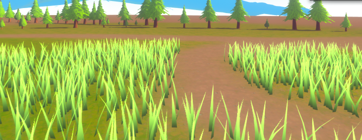
Bigger less detailed grass
One piece of feedback on the shader was that the small circle of detailed grass around the player didn’t look very realistic. To make it feel more natural and immersive, I added a larger circle around the existing one, filled with less detailed grass. This creates the illusion of a continuous grass field stretching further into the distance.
The shader now renders three layers around the player. The innermost layer is highly detailed, while the outer one is simplified. The transition is smooth because the more detailed grass in front visually hides the lower-quality grass behind it, which creates a convincing depth effect.
if (dis < _Radius )

             if (dis < _LowPolyGrassRadius & _LowPolyGrassEnabled < 0.5)
             {
                 //Low poly in distance
                     triStream.Append(GenerateGrassVertex(pos, segmentWidth, segmentHeight, segmentForward, float2(0, t), transformMatrix, grassColor));
             }
I added an extra ring of grass around the detailed one. The top part of the grass still gets generated in detail, so the transition doesn’t feel abrupt. This way, it looks like the grass continues beyond the immediate circle around the player.
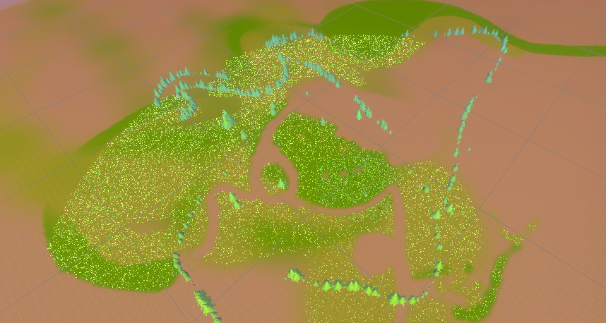
Culling the grass
The current assignment is to ensure the grass only appears on a specific color in the terrain’s surface shader, while still reacting to the player’s position. The circle around the player helps with performance, and early tests showed promising results: the frame rate improved from 97 FPS to 143 FPS so far.
However, I ran into a challenge: it wasn’t possible to read the surface shader’s color data directly in the fragment shader because shaders typically only communicate in one direction. To solve this, I had to restructure the script and move the color-checking logic to a place where I could access the necessary data—either in the tessellation stage or the fragment shader.
I added a line to the tessellation stage that reads the terrain color:
vertexOutput tessVert(vertexInput v)
{
    o.grassFactor = tex2Dlod(_Control, float4(v.texcoord * _Control_ST.xy + _Control_ST.zw, 0, 0)).r;
    return o;
}
Then, I used that value in the fragment shader to prevent grass from being drawn on red parts of the texture (the first layer):
if (grassFactor > _GrassThreshold) return;
Here, _GrassThreshold defines how much red is allowed before grass stops rendering. Because Unity’s terrain system blends colors, this threshold can be adjusted to control where grass appears more precisely.
Since data flow is one-way, I had to define grassFactor and pass it through the pipeline:
float grassFactor : TEXCOORD5;
geometryOutput GenerateGrassVertex(float3 vertexPosition, float width, float height, float forward, float2 uv, float3x3 transformMatrtix)
           {
              float grassFactor = IN[0].grassFactor;
           }
This way, we assign a value to grassFactor and pass it through the geometry stage. This allows each blade of grass to “know” whether it should be drawn based on the terrain’s color.
The rest of the shader remained unchanged. The surface shader still does what it did before we just moved the color reading logic to a more appropriate stage in the rendering pipeline.
The tessellation script is an easy way to ensure that the surface shader and fragment shader can communicate without any problems. The communication simply includes an extra step, which is the tessellation process.
performance
With the grass shader detailed on in a full grassfield without the circle on the fps is: 111 With the grass shader detailed on in a grassfield with the circle on the fps is: 218 With the grass shader with a textrue on the surface and without the circle and grass is fully filled the fps is: 150 With the grass shader with a textrue and the cricle around the player the fps is: 268
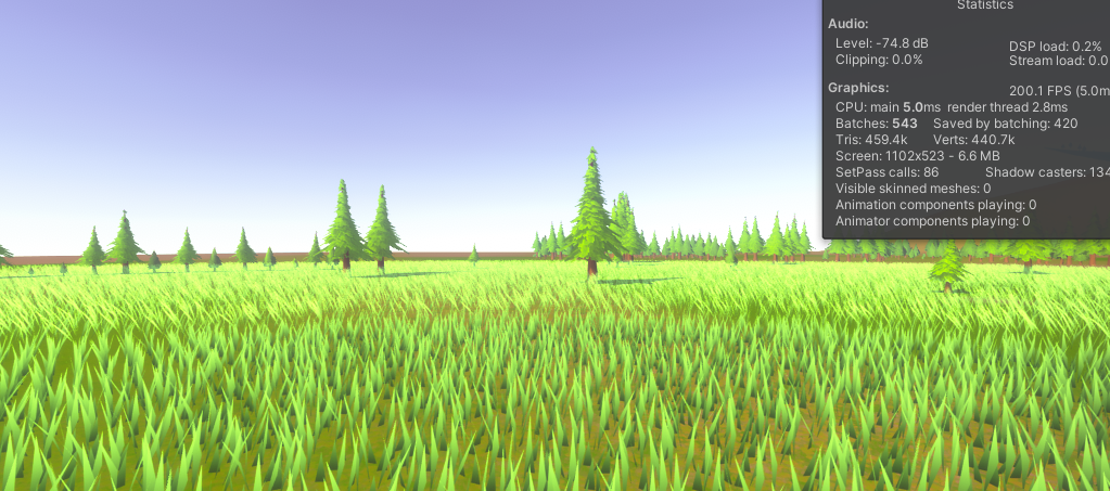
The GPU used for this test is an NVIDIA RTX 4060.
What is clearly visible from these results is that the optimization circle significantly improves the performance of the terrain shader. This technique helps to keep the game well optimized.
The difference in performance between rendering a small, detailed circle of grass around the player and rendering a full field gives a major performance boost without the player even noticing that the grass doesn’t extend infinitely. This creates the illusion of a large grass field while only rendering a small part of it in high detail, which is a powerful optimization strategy.
Issue
Since I generate grass based on vertex density, I observed that when tessellation increases near hills or elevated terrain, the amount of grass becomes noticeably higher. This happens because tessellation subdivides triangles, increasing the vertex count as the player approaches a hills or mountains, which results in more grass blades being spawned in those areas. Consequently, the shader performs best on flat terrain, where the tessellation level and therefore the vertex density remains consistent.
Solution
To address this, grass density could be normalized based on the tessellation factor or controlled using a density map. For example, sampling a density texture in the tessellation or geometry shader could help limit the number of grass blades in highly tessellated regions, maintaining a more uniform appearance across the terrain.
Conclusion
A terrain shader can be created in multiple ways, depending on the desired visual style and performance requirements. You can use either a surface shader or an unlit shader. The most important aspect is ensuring that the shader’s inspector supports multiple texture layers to allow for complex terrain detailing.
Unity’s terrain system provides a color map, but to integrate it properly with the shader, it needs to be multiplied by the tex2D layers. The tex2D function maps the texture’s UV coordinates to those of the color map, ensuring consistent color alignment across all layers. This results in a more cohesive and natural-looking terrain.
Using a tessellation script is a simple way to improve visual fidelity and code readability. It helps organize complex shader code and makes communication between different shader components easier especially when some connections are one-way.
Result
The final result is a fully functional grass shader that dynamically adapts to the player’s position. It includes shadow effects to enhance realism. Developers can customize terrain height and apply multiple layered textures to achieve the desired landscape appearance. Additionally, they can adjust the size of both the inner and outer grass circles surrounding the player.
https://www.youtube.com/watch?v=n7QPfJ4dF9M
Improvemend
When recreating this project and connecting it to a layer, I recommend following the approach used in this research. While this method results in a larger shader with extensive code, breaking the shader into sub-shaders is advised. Sub-shaders help keep the code organized, making it easier to identify which part serves each shader function.
Additionally, keep an eye on hills. In my initial shader version, the number of grass blades remained consistent. However, as I continued developing, I noticed that the number of grass blades would vary as the player approached a hill. Initially, this behavior didn’t occur, and I believe it’s due to the fact that hills gain more detailed meshes when the player gets closer. This is because it helps prevent hills from looking overly pointed if the mesh stayed the same, also is it visible that parts of the object get more detailed mesh in the wireframe look. Since the terrain shader connects to the grass shader, I suspect that as the terrain mesh becomes more detailed at close distances, it may shrink slightly, which in turn adds more grass blades.
Resources
Grass
Random number hlsl. (z.d.). Game Development Stack Exchange. https://gamedev.stackexchange.com/questions/32681/random-number-hlsl
Fixed point vs Floating point number. (z.d.). Stack Overflow. https://stackoverflow.com/questions/7524838/fixed-point-vs-floating-point-number
Art, M. (2020, 8 december). Grass geometry. Grass Geometry. https://www.patreon.com/posts/grass-geometry-1-40090373
Flick, J. (2017, 30 november). Tessellation. https://catlikecoding.com/unity/tutorials/advanced-rendering/tessellation/
Unity Grass Geometry Shader Tutorial at Roystan. (z.d.). https://roystan.net/articles/grass-shader/
Technologies, U. (z.d.). Unity - Manual: Example of Particle System GPU instancing in a Surface Shader. https://docs.unity3d.com/Manual/example-particle-system-gpu-instancing-surface-shader.html
Terrain
Terrain Lit shader | Universal RP | 12.0.0. (z.d.). https://docs.unity3d.com/Packages/com.unity.render-pipelines.universal@12.0/manual/shader-terrain-lit.html
Workflows. (z.d.). https://www.world-machine.com/learn.php?page=workflow&workflow=wfunity
Alastaira. (2013, 7 december). Custom Unity Terrain material / shaders. Alastair Aitchison. https://alastaira.wordpress.com/2013/12/07/custom-unity-terrain-material-shaders/
World of Zero. (2018, 29 april). Building a Custom Unity Terrain Shader [Video]. YouTube. https://www.youtube.com/watch?v=9rSP-ozPs0A
Is unlit shader the same as surface shader with shadows disabled? (2019, 19 september). Unity Discussions. https://discussions.unity.com/t/is-unlit-shader-the-same-as-surface-shader-with-shadows-disabled/758828/3
Microsoft. (n.d.). Predefined macros (DirectX HLSL). Microsoft Learn. https://learn.microsoft.com/en-us/windows/win32/direct3dhlsl/dx-graphics-hlsl-appendix-pre-include
picture made by AI