Introduction
Generating a large space open world game requires a lot of manual work if you’re going to generate the planets yourself. That’s why it could be smart to generate these planets procedurally by using various parameters. This way the developer doesn’t have to create each planet manually, and there could be an infinite amount of different planets. This offers a way more scalable solution for creating a open-world space game.
Research topics
How can a procedural planet generation system be designed to create diverse planets using various parameters that handles the placement of vertexes including continent, mountain and water generation all coloured accordingly using c++ in Unreal Engine?
- How can you create a procedural sphere mesh?
- What techniques can be used to deform the sphere mesh?
- How can a simple solar system be generated?
- How can a material be created to display multiple height levels of the planet?
- How can a level of detail be applied to the planet mesh?
Research
Creating and deforming a procedural mesh
Creating a procedural mesh involves generating a 3D object through code rather than manually modeling it. This approach allows for dynamic and flexible mesh creation, which can be particularly useful in applications like game development, simulations, and procedural content generation. Since the deformation of the vertices is very thightly coupled with the sphere generation, I’ve included it into the same chapter.
Determining the Type of Sphere
First of all, it’s important to determine what kind of sphere you will try to generate. The type of sphere you choose will fundamentally change the way noises get applied to your mesh. Since the triangles in a procedural mesh can vary significantly in size and shape, the noise will not have a uniform impact. Larger triangles may bigger deformations, while smaller triangles will show subtler changes. This can lead to visual inconsistencies if not managed properly.
To demonstrate the different types of spheres, here are some common types of spheres:
UV Sphere: Created by stacking rings of vertices, similar to lines of latitude and longitude on a globe.

Fig. 1. Sphere Wireframe [1].
Cube-mapped sphere: Created by generating 6 faces and then normalizing the distance from the center.
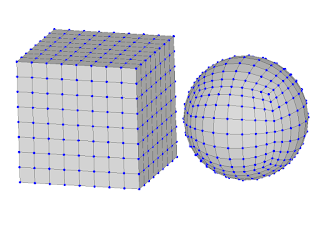
Fig. 2. Cubemapped Sphere [1].
While determining what sphere to use I chose to use the cubemapped sphere. This is because the triangles are very equally sized, and it’s less complicated to create LODs on this mesh because they are subdivisions.
To start I created an actor named ‘ProceduralSphere’. This will hold all of the required data for the planet and will pass it on to it’s children. The planet will hold 6 ‘PlanetFaces’. This is a class that inherits from UProceduralMeshComponent and will handle the visual part of the generation like settings the vertices on the correct spot, and applying the noise data from the ProceduralSphere.
ProceduralSphere
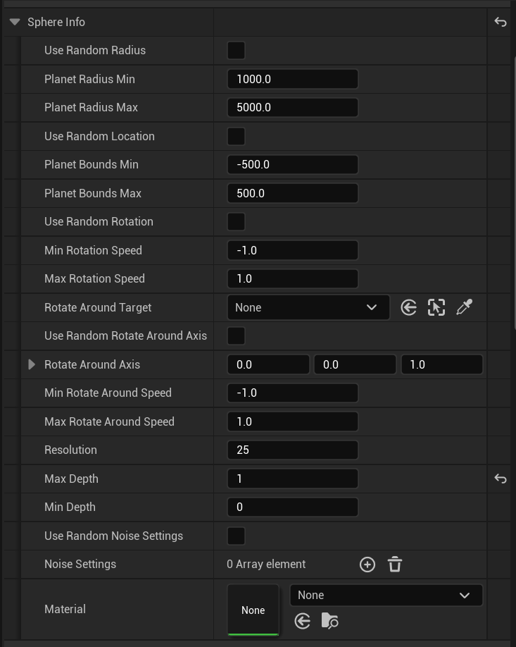
First of all we need to have certain data to start generating the planet. To do this I created a structure called FSphereInfo. In this structure there are various parameters that will later be used in the generation like the radius, noise, random location etc. All of the variables have a ‘base’ value that works good for creating a generic planet. The material is predefined to be a specific material I’ve created. The material itself will be explained in a later chapter.
Now that we have some data we can work with, we can start generating the mesh itself. To do this we need 6 planetfaces. Since I want to be able to have a button in the editor to generate the planet I am caching the planetfaces. This way I don’t have to reassign the components each time I run. When starting to generate the planet, I check the planetface count. If we don’t have exactly 6, we either have to much or too less. So we have to destroy all of the planetfaces, and recreate them.
To randomly set the PlanetInfo I’ve created a function that randomly sets the variables within a certain range. This can be used later on when you’re creating an actor that generates multiple planets, or when you just want a random planet.
Once those variables are set, we can start by generating the different faces, and setting up the noises. We do this by creating 6 faces that are connected to eachother. The locations of the faces are based on a unit vector in a certain direction.
/**
 * Generates a sphere based on 6 procedural meshes using the variables from PlanetInfo
 */
void AProceduralSphere::GenerateSphere()
{
	// Save all directions. This way we can easily access the direction the current face should go to.
	TArray Directions = { FVector::UpVector, FVector::DownVector, FVector::LeftVector, FVector::RightVector, FVector::ForwardVector, FVector::BackwardVector };

	// Loop over the 6 faces we need or have
	for (int i = 0; i < 6; i++)
	{
		UPlanetFace* CurrFace = nullptr;
		// If the current face exists in the PlanetFaces array, we set it, if not we need to create it.
		if (!PlanetFaces.IsEmpty() and PlanetFaces.Num() - 1 >= i)
		{
			CurrFace = PlanetFaces[i];
		}
		else
		{
			// Add a planetface component to this actor. After that we attach it to the root and add it to the planetfaces.
			CurrFace = Cast<UPlanetFace>(AddComponentByClass(UPlanetFace::StaticClass(), false, FTransform::Identity, false));
			AddInstanceComponent(CurrFace);
			CurrFace->AttachToComponent(RootComponent, FAttachmentTransformRules::KeepWorldTransform);
			CurrFace->RegisterComponent();
			PlanetFaces.Add(CurrFace);
		}
		// When the currentface is valid, we generate that face.
		CurrFace->GenerateFace(PlanetInfo, Directions[i], Radius, GetActorLocation());
	}
}
On a side note, if you want to make sure the planet keeps regenerating when changing the planetinfo, we need to override the OnConstruction function. The problem with this however is that this will update instantly and will lagg the editor out very quickly. To solve this I start a timer that waits for 1 second. If there is no change made we regenerate.
/**
 * Runs when any variable of this actor is changed.
 * @param Transform The newly changed transform or this actor
 */
void AProceduralSphere::OnConstruction(const FTransform& Transform)
{
	Super::OnConstruction(Transform);

	// Clear any previous timer.
	GetWorld()->GetTimerManager().ClearTimer(DebounceTimerHandle);

	// We need to use a wrapper function since the GeneratePlanet has variables that can't be set from here.
	GetWorld()->GetTimerManager().SetTimer(DebounceTimerHandle, this, &AProceduralSphere::GeneratePlanetWrapper, DebounceTime, false);
}
PlanetFace
Now that the ProceduralSphere is defined, we need to gather the variables required to set up the planetface. To generate a face we need the data from the procedural planet (planet info), the local up, this way we can define the axis we need to deform to, the radius, and the origin (for the material).
void GenerateFace(const FSphereInfo& PlanetInfo, const FVector& LocalUp, float PlanetRadius, const FVector& Origin);
To be able to generate the vertices we need to calculate the location it’s supposed to be at. To do that we’re using a double for loop.
for (int x = 0; x < PlanetInfo.Resolution; x++)
{
	for (int y = 0; y < PlanetInfo.Resolution; y++)
	{
		int Index = x + y * PlanetInfo.Resolution;
		// Calculate the current percent of all vertices that will be placed
		const FVector2D Percent = FVector2D(x, y) / (PlanetInfo.Resolution - 1);
		// Set the location of the vertex to be at a certain point on the grid
		FVector PointOnUnitCube = LocalUp + (Percent.X - .5) * 2 * AxisA + (Percent.Y - .5) * 2 * AxisB;
		// Normalize the pointoncube to create the sphere instead of cube.
		PointOnUnitCube.Normalize();
		// Apply all sorts of noises to the point
		FVector Vertex = CalculatePointOnPlanet(PointOnUnitCube, PlanetInfo.NoiseSettings, PlanetRadius);
		Vertices.Add(Vertex);
		Normals.Add(Vertex.GetSafeNormal());
		// Calculate the UV for this vertex
		const float U = FMath::Atan2(PointOnUnitCube.Y, PointOnUnitCube.X) / (2 * PI) + 0.5f;
		const float V = FMath::Acos(PointOnUnitCube.Z) / PI;
		UVs.Add(FVector2D(U, V));

		// Create the triangles based on the current vertex in a specific order. Changing this will mess up the generation.
		if (x != PlanetInfo.Resolution - 1 && y != PlanetInfo.Resolution - 1)
		{
			Triangles.Add(Index);
			Triangles.Add(Index + PlanetInfo.Resolution + 1);
			Triangles.Add(Index + PlanetInfo.Resolution);
			Triangles.Add(Index);
			Triangles.Add(Index + 1);
			Triangles.Add(Index + PlanetInfo.Resolution + 1);
		}
	}
}


// Create the procedural mesh after all the calculations are finished
CreateMeshSection(0, Vertices, Triangles, Normals, UVs, TArray<FColor>(), TArray<FProcMeshTangent>(), true);
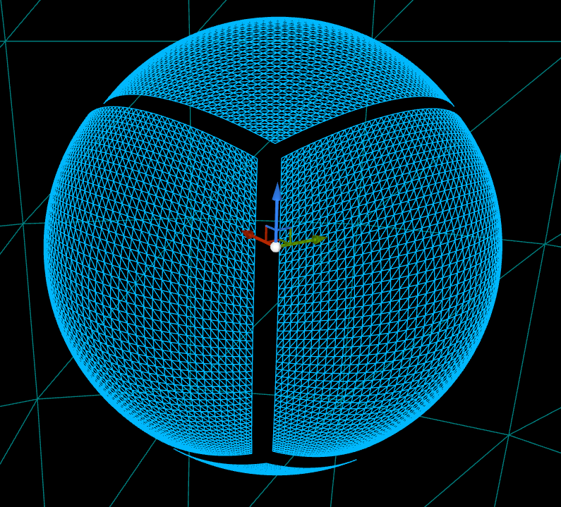
Now that the sphere and the faces are defined, we can see the following result. I’ve dragged the faces itself apart so you can see that it consists of multiple faces.
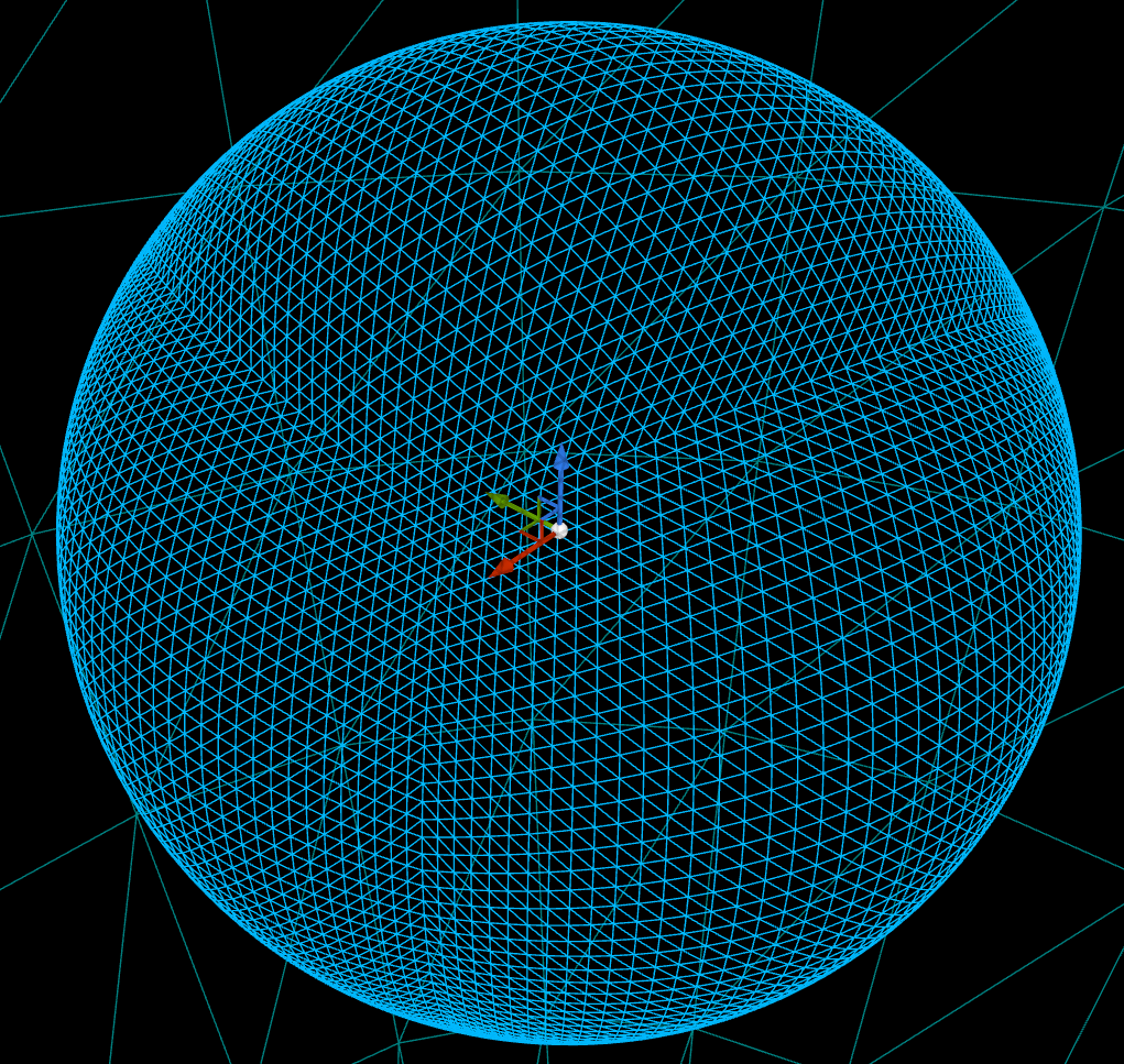
To apply the various noise effects on the vertex we’re performing multiple calculations. These are fine-tuned to make it seem ‘smart’. First of all we’re using a perlin noise as the base value. After that we’re manipulating the noise value according to the variables that can be set in the sphereinfo.
// Loop over all noise settings
for (int i = 0; i < NoiseSettings.Num(); i++)
{
	FNoiseSettings NoiseSetting = NoiseSettings[i];
	if (!NoiseSetting.Enabled) continue; // Don't continue if this setting is disabled

	float Frequency = NoiseSetting.BaseRoughness;
	float Amplitude = 1;
	float NoiseValue = 0;
	// Check if we should use a mask. For the first index this value will be 1
	const float Mask = NoiseSetting.UseFirstLayerAsMask ? FirstLayerValue : 1;
	// Each setting can have multiple layers. Each layer the noisevalue, frequency and amplitude are changed. This will make sure that a deeper level will have less impact, but more roughness.
	for (int j = 0; j < NoiseSetting.AmountOfLayers; j++)
	{
		// We're using perlin noise as the base elevation, and applying various effects ontop of that.
		const float Elevation = FMath::PerlinNoise3D(PointOnUnitSphere * Frequency + NoiseSetting.Center);
		NoiseValue += (Elevation + 1) * .5f * Amplitude;
		Frequency *= NoiseSetting.Roughness;
		Amplitude *= NoiseSetting.Persistance;
	}
	// Make sure the value doesn't go under 0
	NoiseValue = FMath::Max(NoiseValue - NoiseSetting.MinValue, 0.0f);
	// Apply the mask
	NoiseValue *= NoiseSetting.Intensity * Mask;
	TotalNoiseValue += NoiseValue;

	// Set the firstlayer mask if you're on the first index
	if (i == 0)
	{
		FirstLayerValue = NoiseValue;
	}
}
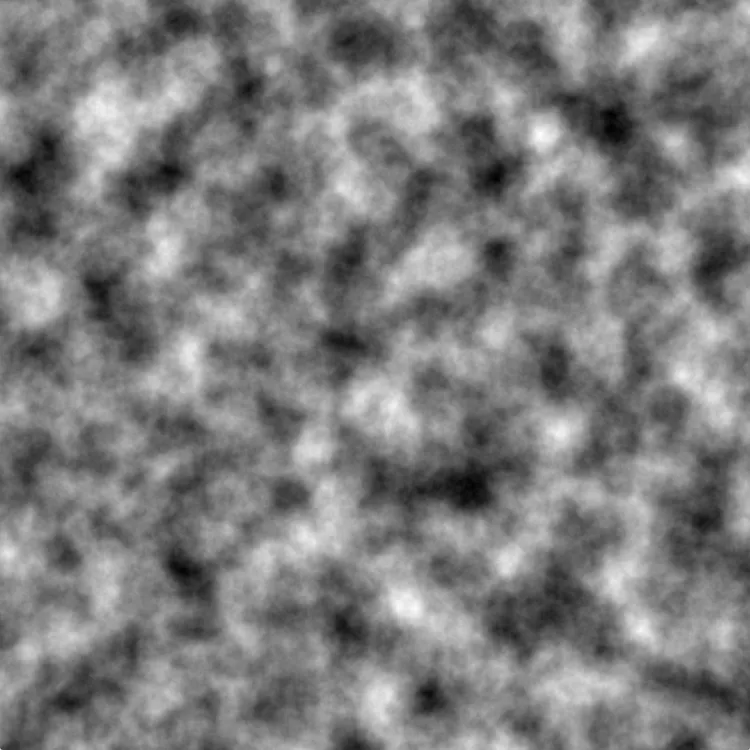
Using this method we can have the following result. This is just a perlin noise. After that when the various effects are applied, it can look like the second picture.
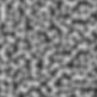
This perlin noise is then transferred onto the vertices itself. With the default values set, it creates this result:
Planet with default settings
These values can be tweaked to create all sorts of different planets. Playing with these values can make anything from nothing, to very spikey planets, to just some hills.
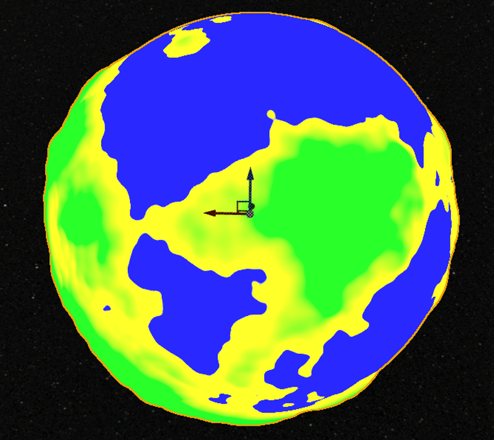
Example with small hills
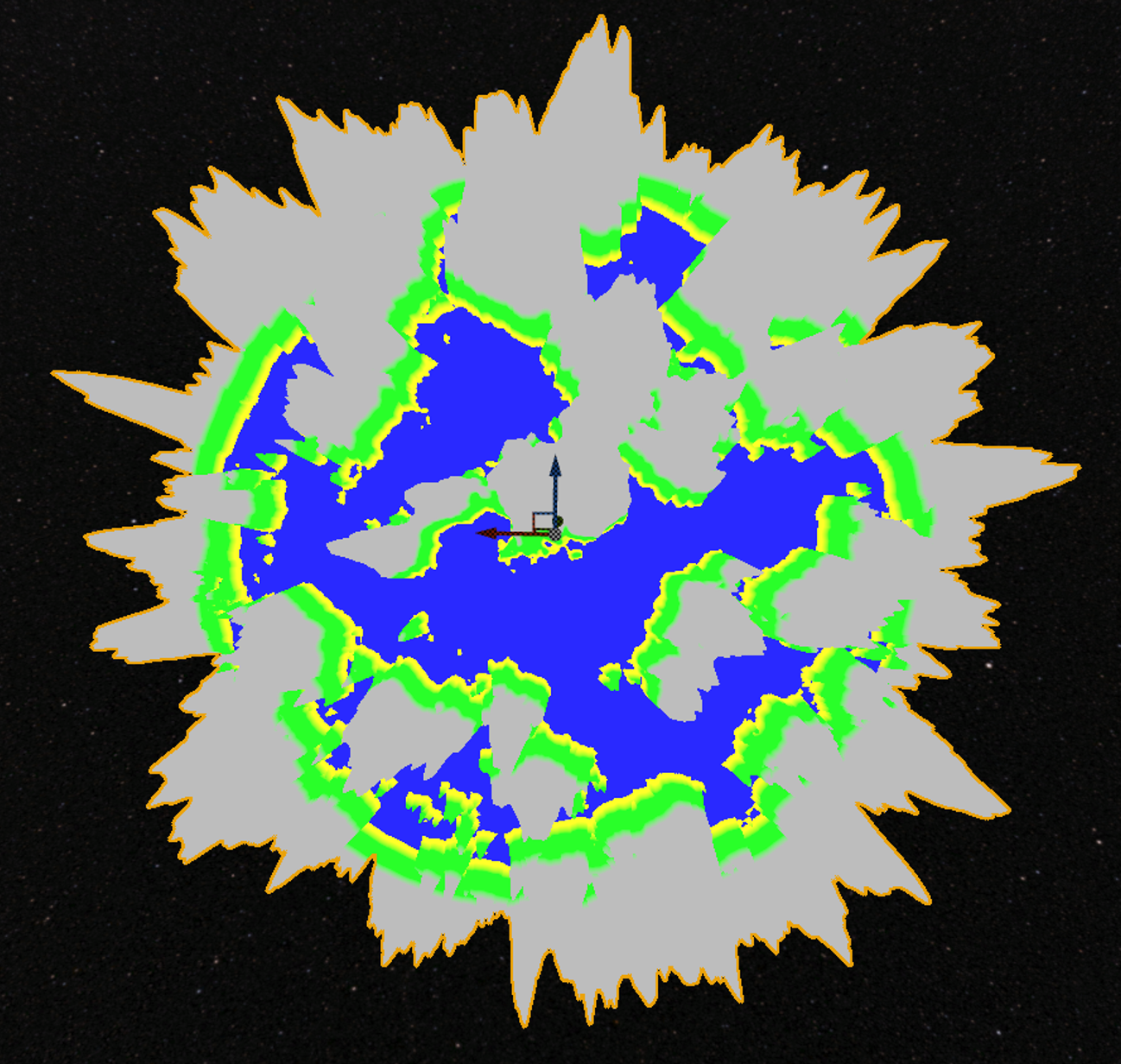
Example with spikey hills
Besides the first layer, you’re able to choose to have multiple layers. Each layer also has an option to use the first layer as a mask. This means that the first layer can be used to generate continents, and the other noise layers are only allowed to continue on that first layer. I’ve made an example where it clearly shows the difference:
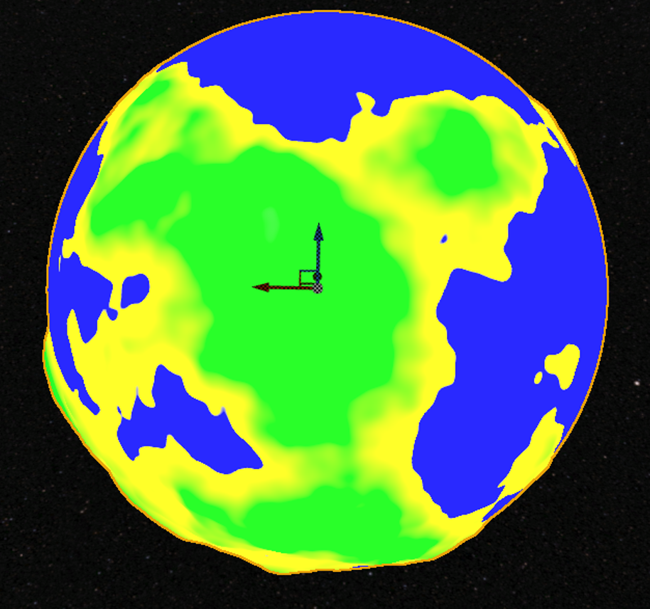
The first layer
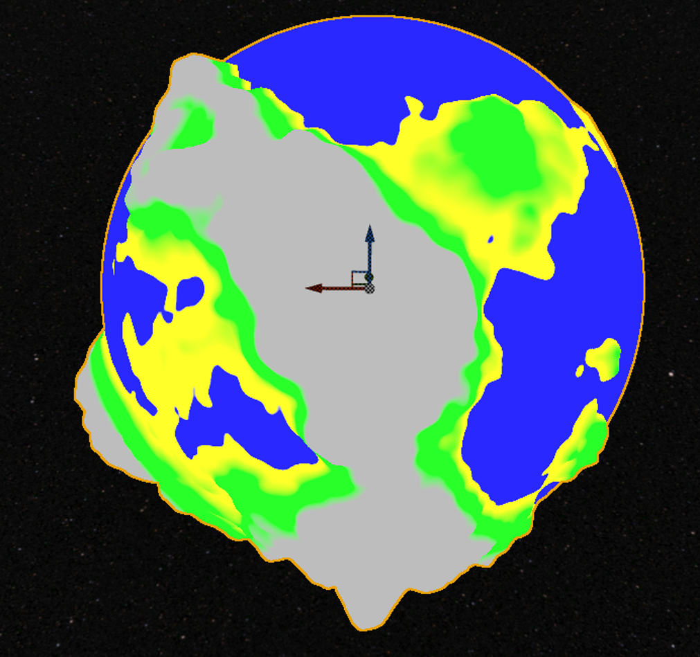
Example without the mask enabled
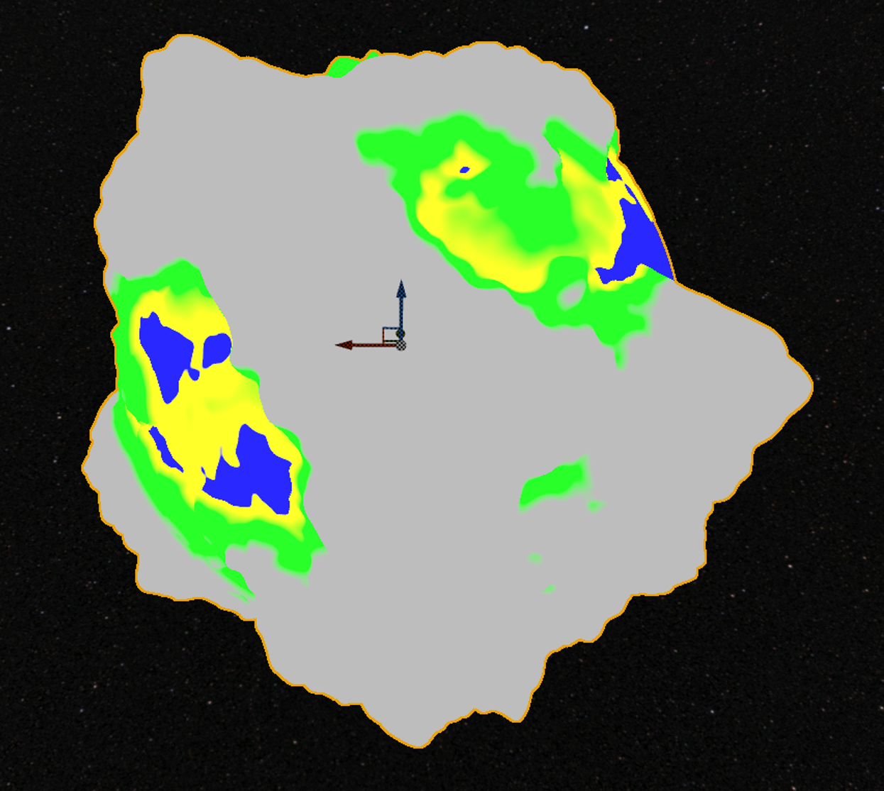
Example with the mask enabled
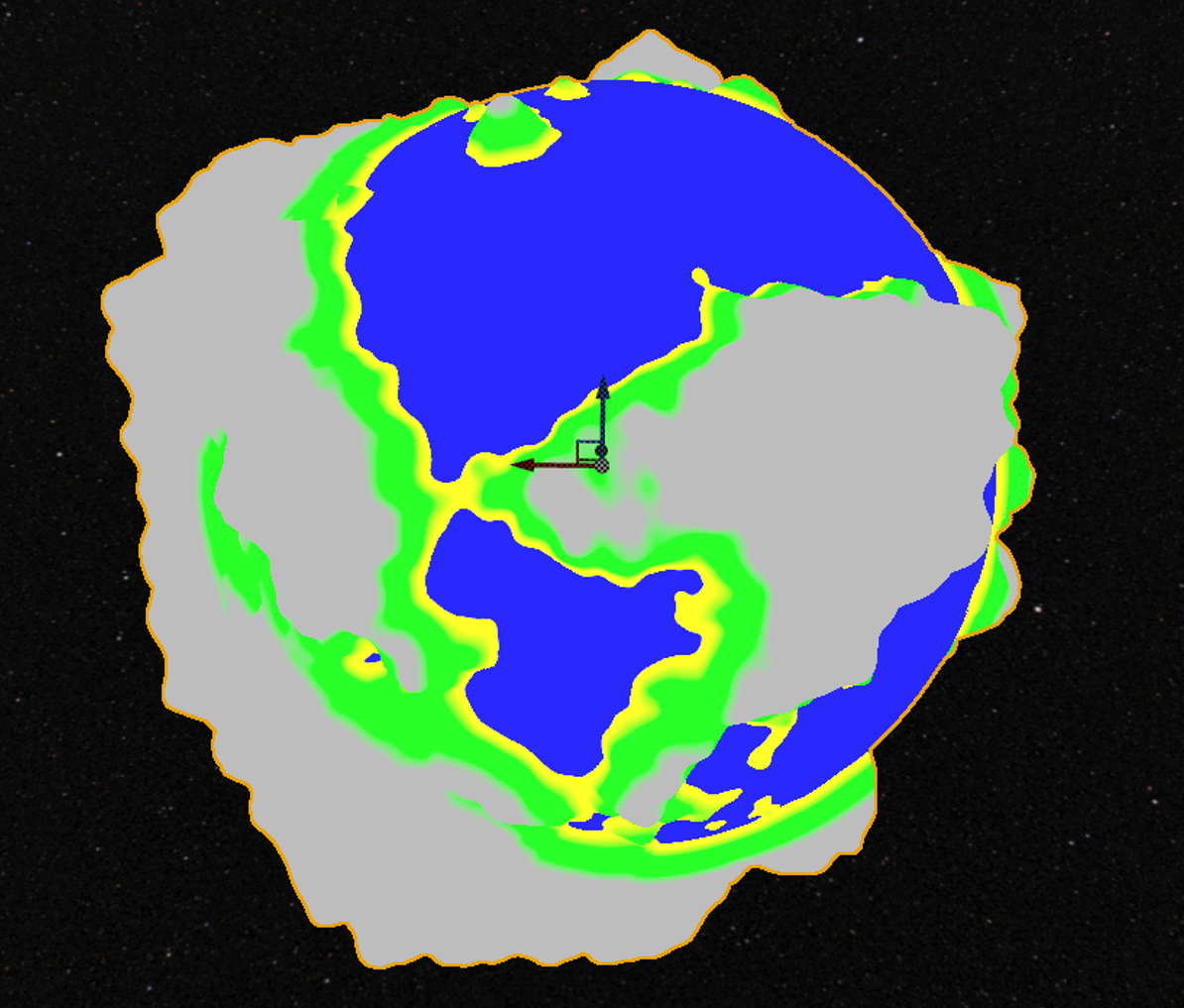
Once all the vertices have been generated, we can pass these values on to the material. This way we can create an adaptive autolandscape material. In this material we’re using the variables set in the planetface to display accurate information. This way you could also make poles on the planet using the faces.
Creating a basic solar system
To create a basic solar system some requirements have to be setup. The following things are, in my opinion, basic requirements:
- A sun
- At least 5 different looking planets
- The possibility for planets to have moons
- Planets and moons rotating around their own axis, and around the parent (either planet or sun)
To set-up these requirements some additions have to be made to the ProceduralSphere. First of all we need more information to be able to generate the solar system based on that. For all spheres we need a rotation speed around itself, and around it’s target. Furthermore we need to be able to set the target that this sphere should rotate around. Besides that a planet should also have an array of moons that can be filled in which is just a struct FSphereInfo.
When the required information is set-up we can create the code for it.
When the information is updated in the outliner, and the planet is regenerated, we want to create a looping timer that will update the rotations of this specific planet. Usually when you want to rotate something around another actor, you’d attach it. However since both spheres can be rotating, this will result in an inaccurate result. That is why some special calculations need to be made to make the spheres rotate correctly.
void AProceduralSphere::RotateSphere()
{
	// Add the rotation around it's own axis
	AddActorWorldRotation(FRotator(0, RotationSpeed * GetWorld()->GetDeltaSeconds(), 0));

	// Only continue if we have a target to rotate around
	if (SphereInfo.RotateAroundTarget == nullptr)
	{
		MovementThisFrame = FVector::ZeroVector;
		return;
	}

	FVector PivotPoint = SphereInfo.RotateAroundTarget->GetActorLocation();

	FVector DirectionToActor = GetActorLocation() - PivotPoint;

	// Calculate the new direction
	FVector NewDirection = DirectionToActor.RotateAngleAxis(RotateAroundSpeed, SphereInfo.RotateAroundAxis);
	FVector TargetMovementThisFrame = FVector::ZeroVector;

	if (SphereInfo.RotateAroundTarget->IsA(StaticClass()))
	{
		// If the target actor also has movement, we need to calculate that in as well.
		AProceduralSphere* Target = Cast<AProceduralSphere>(SphereInfo.RotateAroundTarget);
		TargetMovementThisFrame = Target->MovementThisFrame;
	}
	// Update the location
	FVector NewActorLocation = PivotPoint + NewDirection + TargetMovementThisFrame;
	MovementThisFrame = NewActorLocation - GetActorLocation();
	SetActorLocation(NewActorLocation);

	// Since the material is based on the origin, we need to update the origin as well.
	DynamicMaterial->SetVectorParameterValue("Origin", GetActorLocation());

	for (auto Element : PlanetFaces)
	{
		Element->SetMaterial(0, DynamicMaterial);
	}
}
Now that this is created, you’re able to tweak the speed variables and rotate an infinite amount of planets around eachother like this. I’m assigning the actor the planet should rotate around.
Besides the planet, we need a moon and sun. These are just spheres that have their own material assigned to it. This will be discussed in the material section.
Automatically create moons
To automatically spawn moons around the planets, we need to dynamically check if the amount of moons has changed, and based on that spawn / despawn moons. To do this I override the generatesphere method to add additional functionalities. To track whats removed we save the list of previous info and remove all the moons that exist there. After that we spawn the new moons.
void AProceduralPlanet::GenerateSphere()
{
	Super::GenerateSphere();

	// Destroy all the 'old' moons.
	for (auto LocalMoonInfo : MoonInfoListPrevious)
	{
		LocalMoonInfo.Moon->Destroy();
	}
	MoonInfoListPrevious.Empty();

	// Generate all the moons
	for (int i = 0; i < MoonInfoList.Num(); i++)
	{
		AProceduralMoon* Moon = GetWorld()->SpawnActor<AProceduralMoon>(AProceduralMoon::StaticClass());
		Moon->SetActorLocation(GetActorLocation() + FVector(FMath::RandRange(0.0, 1.0), FMath::RandRange(0.0, 1.0), 0.0) * FMath::RandRange(MoonInfoList[i].MinDistance, MoonInfoList[i].MaxDistance));
		Moon->SphereInfo.RotateAroundTarget = this;
		Moon->GeneratePlanet();

		MoonInfoList[i].Moon = Moon;
	}
	MoonInfoListPrevious = MoonInfoList;
}
Now that the moons are correctly spawning, we can just assign a moon in the outliner and it will spawn automatically. It can happen that these are overlapping, but for this example it’s accepted.
Combining it all
To combine all of this logic, we need a class that will spawn a sun, after that it will generate a random amount of planets around it. I used a distance inbetween the different planets to space them apart, and made them use the random info. This way They will all rotate around the sun at a different speed.
Creating level of detail on the procedural mesh
To create a level of detail system we can do multiple things. First of all I want to create a very basic LOD system, and after that use more advanced techniques to optimize it.
Basic LOD
To create a basic LOD system I need to setup a mapping from LOD level to a certain distance from the player. After that I need to check the distance from the face to the player and if that value is not in the same range as the mapping, we need to update the mesh. To do this I’ve created a function that checks this on tick. This is done for each face.
FVector PlayerPos = GetWorld()->GetFirstPlayerController()->GetPawn()->GetActorLocation();
float dist = FVector::Dist(PlayerPos, Origin);

// Loop over the mapping we've setup. If the LOD should change, we regenerate the face.
for (const auto& Elem : DetailLevelDistances)
{
	if (!(dist > Elem.Value)) continue;

	if (Elem.Key == CurrentLOD) break;

	CurrentLOD = Elem.Key;
	GenerateFace();
	break;
}
To actually use this value we need to change the generateface method to change the resolution. We simply use the resolution as base value, and multiply the currentLOD based on the resolution.
int32 AdaptedResolution = PlanetInfo.Resolution + PlanetInfo.Resolution * CurrentLOD;
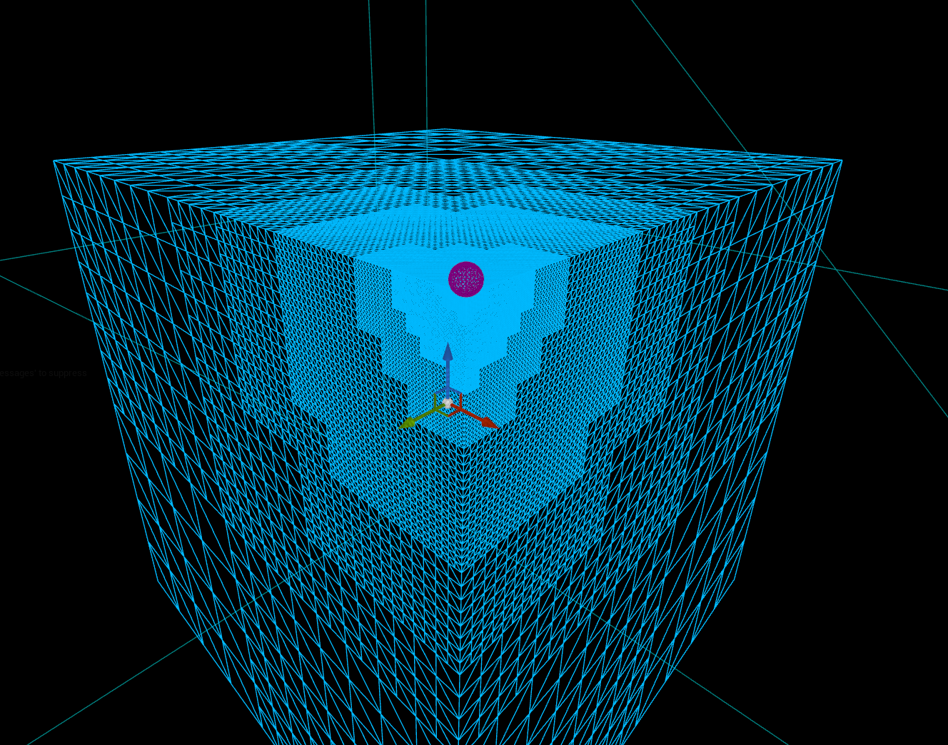
The end result is each face to update based on the distance as can be seen in the gif below.
Advanced LOD
To create a more advanced LOD system I chose to use a quadtree. A quadtree is a data structure to subdivide a specified area into multiple smaller areas. In my specific use case it is very usefull to use this technique to divide my faces into smaller faces. This way you only have to change the LOD in the area you’re currently in, thus improving performance.
To visualize this technique, I’ve created a small sample that generates spheres on the places that the quadtree is generating. This way, you’re seeing that the closer the player comes, the more points are getting generated. This is the foundation of the quadtree [2].
Currently the planet generation is handled in the planetface, and this is just drawing the entire face based on the resolution. To be able to use quadtrees we need to change this so that the generateface method is called for each node and adapt the offset etc so it only generated a part of the face.
First of all we need to generate the quadtree. To do this I basically use the same logic as before, but now I check the distance from the player to the current node.
void UPlanetFace::UpdateQuadtree(FQuadtreeNode& Node, const FVector& CameraPosition)
{
	float Distance = FVector::Dist(CameraPosition, Node.WorldPosition);

	// If the distance is smaller than the current LOD and we're in the range of depth, continue.
	if ((Distance < DetailLevelDistances[Node.Depth] && Node.Depth+1 <= PlanetInfo.MaxDepth) || Node.Depth < PlanetInfo.MinDepth)
	{
		// If the node is a leaf node, we need to update the quadtree. This means that we're creating 4 new children.
		if (Node.IsLeaf())
		{
			const float ChildSize = Node.Size / 2.0f;
			for (int32 i = 0; i < 4; ++i)
			{
				// Calculate the offset of the child
				FVector ChildOffset = ((i & 1) ? AxisA : -AxisA) * ChildSize + ((i & 2) ? AxisB : -AxisB) * ChildSize;
				FVector ChildPosition = Node.RelativePosition + ChildOffset;
				FVector WorldPosition = ChildPosition + LocalUp * PlanetRadius + GetOwner()->GetActorLocation();
				FQuadtreeNode ChildNode = FQuadtreeNode(ChildPosition, ChildSize, Node.Depth + 1, WorldPosition);
				// Add child to list and call the update to recursively update the quadtree.
				Node.Children.Add(ChildNode);
				UpdateQuadtree(ChildNode, CameraPosition);
			}
			ShouldUpdate = true;
		}
		else
		{
			// If it's not a leaf node, we need to update the children.
			for (FQuadtreeNode& Child : Node.Children)
			{
				UpdateQuadtree(Child, CameraPosition);
			}
		}
	}
	else
	{
		// If the distance is bigger than the current LOD, we need to remove
		if (!Node.IsLeaf())
		{
			Node.Children.Empty();
			ShouldUpdate = true;
		}
	}
}
Once the entire quadtree is updated, we check if we should update the current mesh based on if the quadtree changed this frame. If the quadtree has changed, we need to update the entire face. To update the mesh based on the quadtree, a large part of the generation logic needs to be updated. First of all I changed it to generate the vertices and triangles first, and after that generate the mesh.
void UPlanetFace::GenerateMeshDataForQuadTree(FQuadtreeNode& Node)
{
	// If the node is a leaf node, update the vertices and triangles.
	if (Node.IsLeaf())
	{
		TArray<FVector> NodeVertices;
		TArray<int> NodeTriangles;
		GenerateVerticesAndTriangles(Node, NodeVertices, NodeTriangles, TotalTriangleOffset);
		CombinedVertices.Append(NodeVertices);
		CombinedTriangles.Append(NodeTriangles);
		TotalTriangleOffset += NodeVertices.Num();
		return;
	}

	// If the node is not a leaf node, update the children.
	for (FQuadtreeNode& Child : Node.Children)
	{
		GenerateMeshDataForQuadTree(Child);
	}
}
The GenerateVerticesAndTriangles method is basically the ‘old’ generateface method only adapted to the new quadtree method. The largest part that changed is the point placement and the triangle offset. The offset is being changed by the current node depth.
FVector PointOnUnitCube = LocalUp + ((Percent.X - .5) * 2 * AxisA + (Percent.Y - .5) * 2 * AxisB) * (1.0 / FMath::Pow(2.0, Node.Depth));
PointOnUnitCube += Node.RelativePosition / PlanetRadius;

// Create the triangles based on the current vertex in a specific order. Changing this will mess up the generation. The triangleoffset is required to offset the current triangle based on the place it is in the grand scheme of triangles.
if (x != PlanetInfo.Resolution - 1 && y != PlanetInfo.Resolution - 1)
{
	OutTriangles.Add(Index + TriangleOffset);
	OutTriangles.Add(Index + PlanetInfo.Resolution + 1 + TriangleOffset);
	OutTriangles.Add(Index + PlanetInfo.Resolution + TriangleOffset
	OutTriangles.Add(Index + TriangleOffset);
	OutTriangles.Add(Index + 1 + TriangleOffset);
	OutTriangles.Add(Index + PlanetInfo.Resolution + 1 + TriangleOffset);
}
After all vertices and triangles have been generated, we add it to the global list of vertices and triangles, and after that generate the mesh itself. This is still the same code as before.
The end result is the LOD system working based on the distance from the player. This is currently visualised on a cube since that shows it better.
Creating a world material
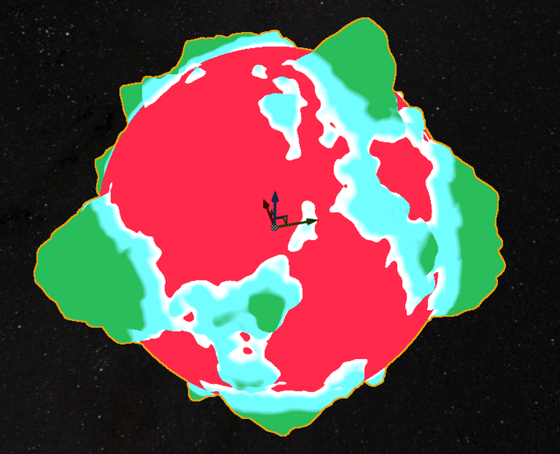
Autolandscape
I’ve created an autolandscape material that lerps from color to color based on the distance from the center point and the planet radius. The colors will have a small transition height, but other than that be their own color. This color is randomized together with the noise info to generate some extraordinary planet colors like the one in the picture.
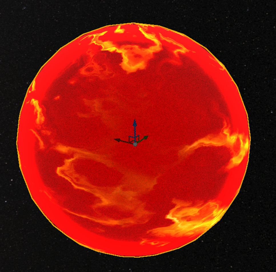
Sun material
For the sun material I chose to use a noise texture and some edge detection to create some small solar flares. This is done by using the dot product of that vertex normal to know if it’s on the edge. If it is we multiply it by a certain value to make it brighter.
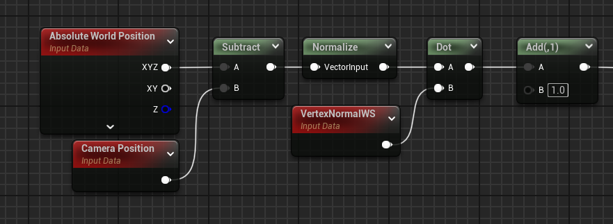
After the noise values and the solar flares have been applied, I added a niagara effect around the sun to give it a more lively look:
Conclusion
In conclusion, this research explored procedural mesh generation techniques to create a diverse and scalable planet generation system within an open-world space game. The core approach involved generating sphere meshes procedurally, using cube-mapped spheres to maintain uniformity in triangle size and make the noise offsets as correct as possible. By utilizing structured noise functions, including Perlin noise and multi-layer masking, the planets could display unique landscapes, from smooth landscapes to rugged terrains. This procedural generation method not only enhanced realism but also reduced the manual workload required to create individual planets, thereby providing a scalable solution to populate an extensive space environment.
Additionally, a basic solar system was developed, with planets orbiting around a central sun, and moons orbiting the planet.
The materials were created for a specific purpose. The autolandscape material was created using the distance from the center. This way the colors could be assigned based on the height. For the sun the material uses noise as a base, and a edge detection method to create a glow effect.
Some things that could be improved upon is using textures to create even more realistic planets. Furthermore the planets could be generated using a heightmap instead of manually offsetting each vertex. The final thing that could be improved is the performance. Currently the performance is better when not using the LOD system, since Unreal Engine handles a large amount of vertices seemlessly.
Sources
- “Sphere wireframe,” Wikipedia, The Free Encyclopedia. Available: https://en.m.wikipedia.org/wiki/File:Sphere_wireframe.svg. Accessed: Oct. 2, 2024.
- “Quadtree Explanation,” YouTube. Available: https://www.youtube.com/watch?v=OJxEcs0w_kE. Accessed: Oct. 9, 2024.
- “Perlin noise,” Wikipedia, The Free Encyclopedia. Available: https://en.wikipedia.org/wiki/Perlin_noise. Accessed: Nov. 1, 2024.
- Y. Scher, “Playing with Perlin noise: Generating realistic archipelagos,” Medium, Available: https://medium.com/@yvanscher/playing-with-perlin-noise-generating-realistic-archipelagos-b59f004d8401. Accessed: Nov. 1, 2024.
- “Procedural mesh generation: UV sphere,” Catlike Coding. Available: https://catlikecoding.com/unity/tutorials/procedural-meshes/uv-sphere/. Accessed: Oct. 2, 2024.
How can a procedural planet generation system be designed to create diverse planets using various parameters that handles the placement of vertexes including continent, mountain and water generation all coloured accordingly.