Abstract
This research is about the development of a glitch effect shader in Unity. The shader makes use of noise maps, color channel displacement, and pixel displacement using HLSL within the built-in Unity rendering pipeline.
Table of Contents
- Abstract
- Table of Contents
- Introduction
- Background research
- Development
- References
Introduction
I first became interested in shaders during my last semester, where I began experimenting with Unity’s Shader Graph to create shaders for the skybox and clouds. While Shader Graph was an easy and accessible way to get started with creating shaders, I heard that the shaders it generates are much more inefficient compared to hand-written shaders. This made me curious about learning how to write my own shaders using HLSL.
I saw this R&D project as a good opportunity to dive deeper into shader creation and to gain a better understanding of how graphics programming works under the hood. I decided to develop a glitch effect shader because it allowed me to explore a variety of shader techniques, including vertex distortion, texture manipulation, and screen-space effects.
Research question
How can an object-based glitch effect shader, including color and shape distortions, be implemented in Unity using HLSL?
The end product should be a shader that can be applied to individual objects, instead of the entire camera as a post processing effect. This shader should make the object appear color shifted and wavy. I also want the shader to display some static over the object. I would like the shader to be highly customizable so I can easily use it in future projects without much effort. The following parameters of the shader should be customizable:
- Intensity of color shifting
- Frequency of distortion waves
- Size of distortion waves
- Speed of static effect
- Strength/opacity of static effect
- Density/size of static effect
I would like to be able to use this shader in any Unity project easily. The shader should be easy to implement in a project and be highly customizable so it can fit well with any project. This shader could fit well in a horror or sci-fi environment.
Background research
Before starting the development of the glitch shader, I wanted to gain some inspiration for the effects so I know what type of effect I exactly wanted to achieve. I also wanted to learn how to set up a simple shader in HLSL and what the basic setup of the shader is, so I have a good starting point for researching the more advanced methods that will come up.
HLSL tutorials
To learn the basics of making a HLSL shader in Unity, I followed two tutorials by Dapper Dino [1] [2]. These tutorials covered the overall structure of the shader file and what it’s functions do, how to add variables so the shader can be tweaked in the editor, and how to add a texture to the object.
Inspiration


Chromatic aberration
Chromatic aberration is an optical phenomenon where different colors focus at slightly different points, leading to discoloration around the edges of objects. This effect usually gets stronger around the edges of the frame. [3]
Multiple exisiting glitch effect shaders make use of Chromatic aberration to add color distortion. [5] [6] [7] For my shader effect, I want to add a similar looking discoloration effect, however since the object should always appear glitched, it doesn’t have to change strength based on the position on the screen.

Development
Color distortion
The color shift effect I want to recreate shows the colors shifting outside of the actual mesh of the object. The vert() function changes the rendered position of the object, and the frag() function changes the color of the pixels on the vertexes of the object. Because I want to change things outside of the object vertex, I thought I should make most of my changes in the vert() function. Later on after adding the color distortion outside of the object, I also wanted to add some slight texture color distortion to make the effect look more complete.
Rendering the object multiple times
I needed to add extra vertices in some way because I want the original object to show up, but also the displaced colors around the object. Only changing the color on the object would not work properly since no pixels outside of the object would change.
I could not find an easy way to add vertices to an object, but I did find out you can add multiple passes to a shader by just adding more Pass blocks. [8] Using this method you can render an object multiple times, and each pass has its own frag() and vert() functions, so I can make a lot of changes on how to render each pass of the object.
I copied the standard Unity-created pass and made each pass only show one of the RGB colors. I lowered the transparency of each pass so you can see them all, and I added an offset value. This did not work at first. I found out that URP doesn’t normally support multiple passes, but the built-in render pipeline does. I started a new project using the built-in render pipeline, and this worked. [9]
Adding transparency
The recolored objects did not show up as transparent, even after setting the subshader type to transparent with Tags { "RenderType"="Transparent" "Queue"="Transparent" } and changing the alpha value of the texture. This is because the RenderType and Queue only change the order in which the objects should render, and they don’t actually handle rendering the transparency. This can be done using the Blend command. [20] By using Blend SrcAlpha OneMinusSrcAlpha you can make it work properly. [10] This successfully made the colored objects appear transparent, however this didn’t really achieve the look I was going for:

I thought that if I render three objects with each a color assgined to the R, G, or B colors and make them all slightly transparent, they would combine back into the original color when stacked on top of eachother. However, this did not work and resulted in the color of the last pass taking over most of the color of the original texture (blue in this case). To fix this, I decided to add another pass to the shader that just renders the object like normal, this way the original texture is always clearly visible and the blending of the colors doesn’t look weird.
I had the issue that the normal pass didn’t render properly on top of the other layers:

I fixed this issue by moving the pass of the normal object to the top of the order instead of at the bottom.
Rendering was better but still incorrect:

I wanted the normal object to show up on top of the discolored objects. First I tried to lower the Z value based on the chromatic aberration strength, however this just made them disappear. When setting it to 0 they appeared behind the normal object exactly how I wanted.
I wanted the color shift to be brighter and more noticable. After looking at the Unity documentation of the Blend command, I found that there are several blend types. I tried different combinations and ended up with Blend SrcAlpha DstAlpha, which gives the color shift a brighter appearance.
Code snippet of one of the color vertex displacement:
v2f vert (appdata v)
{
    v2f o;

    // animate the effect
    _ChromaticAmount *= sin(_Time.y * _ChromaticAnimSpeed);

    o.vertex = UnityObjectToClipPos(v.vertex);

    // displace this color
    o.vertex.x += _ChromaticAmount;

    // render behind normal object
    o.vertex.z = 0;

    o.uv = TRANSFORM_TEX(v.uv, _MainTex);
    UNITY_TRANSFER_FOG(o,o.vertex);
    return o;
}

fixed4 frag (v2f i) : SV_Target
{
    // sample the texture
    fixed4 col = tex2D(_MainTex, i.uv);
    // render only one color
    col.b = 0;
    col.g = 0;
    col.a = _TransparencyAmount;
    // apply fog
    UNITY_APPLY_FOG(i.fogCoord, col);
    return col;
}
Texture color distortion
The effect didn’t look quite complete though. The color distortion around the object looked good, but it didn’t make a lot of sense that the object itself wasn’t discolored. To add discoloration to the texture of the object, I made a new UVs for each color, all with an offset:
float2 redUv = i.uv -= float2(_ChromaticAmount, 0);
float2 greenUv = i.uv += float2(0, _ChromaticAmount);
float2 blueUv = i.uv += float2(_ChromaticAmount, 0);
Then I used those UVs to create new textures with the offset:
float4 redCol = tex2D(_MainTex, redUv);
float4 greenCol = tex2D(_MainTex, greenUv);
float4 blueCol = tex2D(_MainTex, blueUv);
By getting the R value of the red color, the G value of the green color, and the B value of the blue color and combining them, it creates the discolored look I’m going for:
fixed4 combinedCol = tex2D(_MainTex, i.uv);

combinedCol.r = redCol.r;
combinedCol.g = greenCol.g;
combinedCol.b = blueCol.b;
I combined this with the normal texture and added a _ChromaticTextureMultiplier variable so the strength of the effect on the texture can be tweaked easily. I added it as a slider in the Unity inspector with a range of 0-1, where 0 shows the original texture without any discoloration, and 1 fully shows the discolored texture.
To make the object more flickery and add to the glitch effect, I made the texture discoloration and vertex distortion animate using sin time. The speed of this can be set using the _ChromaticAnimSpeed variable.
| Before | After |
|---|---|
 |  |
The result is the following code for discoloring the texture:
fixed4 frag (v2f i) : SV_Target
{
    _ChromaticAmount *= sin(_Time.y * _ChromaticAnimSpeed);

    // sample the texture
    fixed4 col = tex2D(_MainTex, i.uv);

    float2 redUv = i.uv -= float2(_ChromaticAmount * _ChromaticTextureMultiplier / 2, 0);
    float2 greenUv = i.uv += float2(0, _ChromaticAmount * _ChromaticTextureMultiplier / 2);
    float2 blueUv = i.uv += float2(_ChromaticAmount * _ChromaticTextureMultiplier / 2, 0);

    float4 redCol = tex2D(_MainTex, redUv);
    float4 greenCol = tex2D(_MainTex, greenUv);
    float4 blueCol = tex2D(_MainTex, blueUv);

    fixed4 combinedCol = tex2D(_MainTex, i.uv);

    combinedCol.r = redCol.r;
    combinedCol.g = greenCol.g;
    combinedCol.b = blueCol.b;

    // apply fog
    UNITY_APPLY_FOG(i.fogCoord, col);

    return col * (1 - _ChromaticTextureMultiplier) + combinedCol * _ChromaticTextureMultiplier;
}
Overlapping issues
The color channels rendered behind objects that were further away, while the object itself rendered just fine.

This was fixed by changing the Z value of the vertices. Instead of setting them all to 0, they are now 0.005 lower than their current Z value.

Noise
Adding noise using a texture
A common method to use noise in a shader is by using a pre-made noise texture that can be easily mapped to the object. I created my own noise texture in Affinity Photo by making a solid white image and then adding a noise filter to it:

By multiplying the colors of the main texture and the noise map, a noise effect can be created:

Using the following code:
// sample the main texture
fixed4 col = tex2D(_MainTex, i.uv);

// sample the noise texture
fixed4 noiseCol = tex2D(_NoiseMap, i.uv);

// combine main and noise texture colors
col.r = col.r + noiseCol.r * _NoiseStrength;
col.r = clamp(col.r, 0, 1);
col.g = col.g + noiseCol.g * _NoiseStrength;
col.g = clamp(col.g, 0, 1);
col.b = col.b + noiseCol.b * _NoiseStrength;
col.b = clamp(col.b, 0, 1);
Mapping texture to screen space
This works for a basic noise effect, however it’s currently wrapped around the object using the object’s UV. This creates some problems:
- When looking at the object from a distance, the noise effect becomes almost unnoticable:

- You can see the noise follow the object’s shape, which makes it not uniform across the object:

These issues can be fixed by mapping the noise texture to the screen’s UV instead. Unity has a ComputeScreenPos function that can be used to map textures to screen space instead of world space. With the following code, with the formula listed on their page, you can get a UV map of the screen: [11]
struct v2f
{
    ...
    float4 screenPos : TEXCOORD1;
};

v2f vert (appdata v)
{
    v2f o;
    o.vertex = UnityObjectToClipPos(v.vertex);
    o.uv = TRANSFORM_TEX(v.uv, _MainTex);
    o.screenPos = ComputeScreenPos(o.vertex);
    return o;
}

fixed4 frag (v2f i) : SV_Target
{
    float2 noiseUv = screenUV;
    noiseUv = screenUV + float2(_Time.y * _NoiseSpeed, _Time.y * _NoiseSpeed); // move the UV over time by with a speed multiplier.
}
By mapping the texture to the screen-space instead of the world-space, this solves the previously described issues and looks as follows:

Generating noise in HLSL
To generate noise in Unity using HLSL, a common approach is to create a function that generates pseudo-random values by manipulating input values like the object’s position or time. There is no built-in function in HLSL that does this, so you have to make one yourself. [15]
A common way to generate values that result in noise is to take the fractional part of a mathematical operation, such as the sine of a dot product between two arbitrary numbers. This creates a seemingly random output that can be turned into noise when mapped to the pixels on the screen. [12] [13] [14]
For generating noise values, I used the following function:
float noise(float2 p)
{
    // Generate a random value based on UV coordinates, using sine for randomness
    float n = sin(dot(p, float2(12.9898, 78.233)));
    return frac(sin(n) * 43758.5453); // Returns a value between 0 and 1
}
This gives the following result:

I used the same values that Unity uses for the Simple Noise node in Shader Graph to make sure the noise looks right. The values 12.9898, 78.233, 43758.5453 can be tweaked to achieve different patterns of noise. For example, if you change these to rounded numbers 13, 79, 43759, you can start to see more lines appearing in the noise:

Vertex distortion
Using sine time I animated the vertex of the object side to size. I added Speed, Strength, and Wave Amount properties. By setting the speed and wave amount very high this looks like it can help out a lot of with the flickeriness that I want the shader to have:

However, this effect doesn’t quite look like what I was going for as it still looks very jagged at some parts and it doesn’t work on objects with few vertices, like cylinders and cubes:

The effect is based on the tutorial by Dapper Dino about vertex manipulation. [2]
Pixel displacement
To create an effect that more closely matches what I’m looking for, vertex distortion is not the solution as it doesn’t look how I want it to look and it doesn’t work properly on object with a low amount of vertices.
Vertex and Fragment functions
First, I tried doing this in one pass. Changing anything in the vertex function didn’t work because you can only work with the object’s existing vertices. You can’t create more vertices on the object to give it more detail, for example. Changing anything in the fragment function didn’t work properly either, because the pixels on the object cannot move outside of the vertex, which is needed for the effect I wanted to achieve.
Vertex function changes the actual shape of the object. Pixels cannot be rendered outside of this vertex. Fragment function changes the color of the pixels inside of the vertex.
The effect I wanted to achieve didn’t seem to be doable in just one pass, so I decided to split it into two passes. The object gets rendered in two parts, where each part of the object can be moved individually.
Implementation in Unity
First I created a very small 2x2 pixel texture with white at the top and black at the bottom:

It might look more smoothed out on the page because I changed it’s size in markdown so you can see it properly, but it is actually 2x2 pixels.
This texture gets rendered in screen space, in the same was as described before, with the texture set to Repeat so it infinitely loops over the screen:

The parts on the object where white pixels of the texture are displayed should be rendered like normal in the first pass. This is done using the following code:
col.a = (rowOverlay.r + rowOverlay.b + rowOverlay.g) / 3;
For the second pass, the black pixels of the texture should be rendered like normal. This can be done by inverting the formula:
col.a = 1 - (rowOverlay.r + rowOverlay.b + rowOverlay.g) / 3;
Because the first pass renders the white parts and the second pass renders the black parts, the entire object is rendered again. When the offset it set to 0, the object appears as normal in the exact same place as before. By moving the first pass to the left of the screen and the second pass to the right of the screen, the effect I was looking for can be achieved:

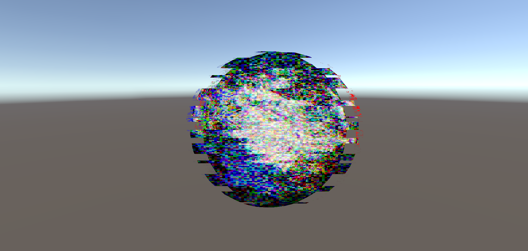
Because the seperation of the two parts of the object is done in the fragment shader, this effect is not dependant on the vertex anymore, which makes this effect work on any object of any shape. For example, with a sphere:

The code for the second pass is the same, except for the formula of the texture transparency. This formula has been inverted to make the black parts show the texture instead of white:
Row size based on object position
While the effect looks good when looking at it from close by, it gets less and less noticable the more you move away from it. This is because the texture is rendered in screen space. When you move away from the object it gets smaller on the screen, while the screen space texture stays the same size. When the object is far away, this makes the rows in the texture look bigger than they should be.
This can be fixed by calculating the distance between the camera position and the object’s position. This can be done with the following code: [16] [17]
float3 objectPosition = mul(unity_ObjectToWorld, float4(0, 0, 0, 1)).xyz;
float3 cameraPosition = _WorldSpaceCameraPos;
float distanceToCamera = distance(objectPosition, cameraPosition);
Then, the size of the texture can changed based on how far the camera is from the object:
float adjustedRowSize = _RowSize * distanceToCamera;
float2 screenUV = i.screenPos.xy / i.screenPos.w * adjustedRowSize + _Time * _RowMoveSpeed;
Render overlapping issues
Rendering the same object twice in the same position introduced some issues. Even though the objects are transparent, the transparent pixels still block the other pass of the object from rendering. I tried multiple methods to try to fix this issue
| No ZTest | Added small Z amount to second pass | Added ZTest Always | Adding more Z amount | ZWrite Off |
|---|---|---|---|---|
| Only the right side of the object renders. | The top of the object now also renders. | =Renders properly on its own but renders over other objects that are closer. | Changed from 0.0001 to 0.005. Now renders properly unless you are too close to the object. This is linked to the Near clipping plane on the camera, which can be changed. This is less apparant on the actual main camera compared to the scene view camera. | Renders properly, even when very close to the camera. |
 |  |  |  |  |
The solution to the problem was to set ZWrite to Off. This would normally automatically happen to semi-transparent objects, however by doing this manually it fixed the issue. [21]
Shader performance
So far, all the shaders have been made in seperate shader files. This made it easier to create the individual effects. However, the end product should be a single shader that includes all the previous effects so it can be put on an object. Because the Chromatic Aberration effect takes 4 passes and the displacement effect takes 2 passes, and the displacement effect should be applied to each of the colors from the Chromatic Aberration effect, this means that there are 4 x 2 = 8 passes needed in the shader. This sounded like a lot to me, and I thought it could possibly turn into a performance issue when adding the effect to models with a high complexity. After merging all the effects together into one shader, I decided to test the shader’s performance to see if this was actually the case.
I created a model of a sphere with a high poly count (77.760 triangles):

When viewing this model in Unity using the default white material/shader, it reports that there are 390.5k triangles being rendered. There were other objects in the scene and Unity always reports a way higher number of triangles because of lighting and the skybox, so this is not unusual. [22]

When applying my shader, it reports 623.8k triangles. Even though the shader uses 8 render passes, the amount of triangles it’s rendering is only about 1.6x more. When comparing the FPS, it did go down from 273 FPS to 237 FPS, however it is still performing just fine. The CPU only got 0.5ms extra latency, and the render thread (GPU) doesn’t seem to have changed much at all.

After comparing my shader to the default Unity shader on a high-poly object, it seems like my concern for performance with my shader was unjustified, as it performs just fine.
Results
This research set out to explore what is needed to make a glitch effect shader in Unity using HLSL, featuring color shifting, shape distortion, and static effects. After merging the all the individual effects together, the end result is a performant glitch shader that can be easily applied to different objects, and customized to create different effects:
| Bed | Generator | Lava Lamp |
|---|---|---|
 |  |  |
Reflection
I am really happy with the end result. I think the shader looks cool and is very versitile. I enjoyed experimenting with shaders and finally learning how to make shaders the ‘proper’ way, instead of with Shader Graph. Diving into HLSL and more advanced techniques helped me understand what I was doing and how things worked a lot more than when I was using Shader Graph during my previous semester.
I had a bit of a slow start, but once I started working in Unity I kept progressing nicely. Though, during this project I think I definitely put more effort into the shader itself than the research. I ended up researching and experimenting a lot for this project while I was trying to get the hang of HLSL, however I did not spend as much time as I probably should have on properly documenting my progress. When I was working on the shader, I did write down my sources and some notes so I could turn them into a proper research, however I waited until the last week to fully turn them into a research article. While I did cover a lot of techniques, I feel like I could have explained my findings and decisions in more detail if I had spent more time on it throughout the entire project.
Future work
In the future, this shader could possibly be developed for the URP pipeline instead of the built-in Unity rendering pipeline. When I discovered that URP didn’t easily support multi-pass shaders, I chose the easy option and just switched the built-in pipeline. However, the URP pipeline is also widely used and with the current implementation of the shader, it won’t work with URP.
References
[1] Dapper Dino, “Writing Shaders In Unity - Basic Shader - Beginner Tutorial,” YouTube. Jul. 01, 2018. [Online]. Available: https://www.youtube.com/watch?v=bR8DHcj6Htg
[2] Dapper Dino, “Writing Shaders in Unity - Vertex Manipulation - Beginner tutorial,” YouTube. Jul. 05, 2018. [Online]. Available: https://www.youtube.com/watch?v=NdKry7MCPM0
[3] Pixel Prophecy, “What is Chromatic Aberration? (And why?),” YouTube. Apr. 17, 2020. [Online]. Available: https://www.youtube.com/watch?v=oE8Zjr5NJrM
[4] “Post processing effects: Chromatic aberration - Unity Learn,” Unity Learn. https://learn.unity.com/tutorial/post-processing-effects-chromatic-aberration
[5] Binary Lunar, “Unity Shader Graph Tutorial: Creating a horror glitch Effect,” YouTube. Dec. 27, 2022. [Online]. Available: https://www.youtube.com/watch?v=VgBv6OrYY7E
[6] H. Alisavakis, “My take on shaders: Glitch image effect,” Sep. 23, 2017. https://halisavakis.com/my-take-on-shaders-glitch-image-effect/
[7] Coolok, “glitch2,” Shadertoy, Jun. 21, 2017. https://www.shadertoy.com/view/4dXBW2
[8] Unity Technologies, “Unity - Manual: Add a shader pass in a custom shader,” Apr. 05, 2025. https://docs.unity3d.com/Manual/writing-shader-create-shader-pass.html
[9] maxkcy, “Multi-pass shader not working, only calls a single pass?,” Unity Discussions, Feb. 09, 2024. https://discussions.unity.com/t/multi-pass-shader-not-working-only-calls-a-single-pass/335743
[10] Digvijaysinh Gohil, “How to write Transparent shader in URP - Unity 6,” YouTube. Jan. 12, 2025. [Online]. Available: https://www.youtube.com/watch?v=GuJ6Pe6amIw
[11] Unity Technologies, “Unity - Manual: Use built-in shader functions in the Built-In Render Pipeline.” https://docs.unity3d.com/Manual/SL-BuiltinFunctions.html
[12] P. G. Vivo, “Noise,” The Book of Shaders, 2015. https://thebookofshaders.com/11/
[13] Unity Technologies, “Simple Noise Node | Shader Graph | 7.1.8,” Oct. 18, 2023. https://docs.unity3d.com/Packages/com.unity.shadergraph@7.1/manual/Simple-Noise-Node.html
[14] Ronja, “White noise,” Ronja’s Tutorials, Sep. 02, 2018. https://www.ronja-tutorials.com/post/024-white-noise/
[15] Barney Codes, “Using noise in shaders (texture blending),” YouTube. Oct. 22, 2023. [Online]. Available: https://www.youtube.com/watch?v=LjsRKfkBi_A
[16] “SHADER: Get *object* position or distinct value per *object*,” Unity Discussions, Nov. 20, 2011. https://discussions.unity.com/t/shader-get-object-position-or-distinct-value-per-object/31873
[17] Unity Technologies, “Unity - Manual: Built-in shader variables reference,” Apr. 05, 2025. https://docs.unity3d.com/Manual/SL-UnityShaderVariables.html
[18] AquaBomber, “How can I create this weird style?,” Reddit, Mar. 05, 2025. https://www.reddit.com/r/Unity3D/comments/1j3zk58/how_can_i_create_this_weird_style/
[19] LSToast, “BEAT SABER BUT MODDERS WENT INSANE (Extra Sensory II FULL LIVE EVENT),” YouTube. Jan. 19, 2025. [Online]. Available: https://www.youtube.com/watch?v=gE0oBIy6rMA
[20] Unity Technologies, “Unity - Manual: Blend command in ShaderLab reference,” Apr. 05, 2025. https://docs.unity3d.com/Manual/SL-Blend.html
[21] Unity Technologies, “Unity - Manual: ZWrite command in ShaderLab reference,” Apr. 05, 2025. https://docs.unity3d.com/Manual/SL-ZWrite.html
[22] jRocket, “Why are my triangle counts so high?,” Unity Discussions, Oct. 01, 2015. https://discussions.unity.com/t/why-are-my-triangle-counts-so-high/599798